WIRELESS ENERGY TRANSFER
MOHD NASUHA BIN MOHAMAD ZIN
This report is submitted in partial fulfillment of the requirement for the award of Bachelor of Electronic Engineering (Industrial Electronic) With Honours.
Faculty of Electronic and Computer Engineering Universiti Teknikal Malaysia Melaka
ii
UNIVERSTI TEKNIKAL M ALAYSIA M ELAKA
FAKULTI KEJURUTERAAN ELEKTRONIK DAN KEJURUTERAAN KOM PUTER
BORANG PENGESAHAN STATUS LAPORAN
PROJEK SARJANA M UDA II
Tajuk Projek : WIRELESS ENERGY TRANSFER
Sesi Pengajian : SESI 2010 / 2011
Saya MOHD NASUHA BIN MOHAMAD ZIN mengaku membenarkan Laporan Projek Sarjana Muda ini disimpan di Perpustakaan dengan syarat-syarat kegunaan seperti berikut:
1. Laporan adalah hakmilik Universiti Teknikal M alaysia M elaka.
2. Perpust akaan dibenarkan m em buat salinan unt uk t ujuan pengajian sahaja.
3. Perpust akaan dibenarkan m em buat salinan laporan ini sebagai bahan pert ukaran ant ara inst it usi
pengajian tinggi.
4. Sila t andakan ( √ ) :
SULIT*
* (M engandungi maklumat yang berdarjah keselamat an atau
kepent ingan M alaysia sepert i yang t ermaktub di dalam AKTA
RAHSIA RASM I 1972)
TERHAD* * * * (M engandungi maklumat t erhad yang t elah dit ent ukan oleh organisasi/ badan di mana penyelidikan dijalankan)
TIDAK TERHAD
Disahkan oleh:
__________________________ ___________________________________
iii
“I hereby declare that this report is the result of my own work except for quotes as cited in the references.”
Signature :………..
Author : MOHD NASUHA BIN MOHAMAD ZIN
iv
“I hereby declare that I have read this report and in my opinion this report is sufficient in terms of the scope and quality for the award of Bachelor of Electronic Engineering
(Industrial Electronic) With Honours.”
Signature : ……….
Supervisor’s Name : MISS NAJMIAH RADIAH BINTI MOHAMAD
v
vi
ACKNOWLEDGEMENTS
I would like to acknowledge and grateful for the guidance of Allah that always gives me the ideas to solve my problems. I also thankful to my parents who have been a giant strength and support to me in my life and in my studies. Also not forget to the people close to me who have supported me throughout my education. I love them dearly.
I would like to acknowledge and thank the faculty supervisor who made this work possible. I cannot say enough about Engineer Miss Najmiah Radiah Binti Mohamad. Her belief and support towards his students is excellent. I am grateful for her help spent many hours patiently answering my questions and troubleshooting with me. Her help and instruction was invaluable and sincerely appreciated.
vii
ABSTRACT
viii
ABSTRAK
ix
TABLE OF CONTENTS
CHAPTER TITLE PAGE
1
PROJECT TITLE
CONFIRMATION OF STATUS REPORT FORM DECLARATION SUPERVISOR DECLARATION DEDICATION ACKNOWLEGMENT ABSTRACT ABSTRAK
TABLE OF CONTENTS LIST OF TABLE
LIST OF FIGURE LIST OF APPENDIX
INTRODUCTION
1.1. Early History of Wireless Energy Transfer 1.1.1 Nikola Tesla
1.1.2 MIT Scientist 1.2 Problem Statement 1.3 Objective
1.4 Scope of Work 1.5 Methodology 1.6 Thesis Outline
x
2
3
4
THEORETICAL REVIEW
2.0 Understanding the Concept of Electromagnetic Inductive Coupling.
2.1 Concept of Electromagnetism 2.2 Electromagnetic Induction 2.3 Resonance Frequency
2.4 Resonance with Capacitor and Inductor 2.5 Resonant Energy Transfer
2.6 Resonant Coupling 2.7 Basic of Inductor
2.8 Quality Factor of Inductor 2.9 Construction of Inductor 2.10 Multilayer Air Core Inductor
LITERATURE REVIEW
3.1 Wireless Energy Transfer via Microwave 3.1.1 The Advantages and Disadvantages of WET via Microwave
3.2 Wireless Energy Transfer via Laser
3.3 Wireless Energy Transfer via Magnetic Resonant Coupling
RESEARCH METHODOLOGY
4.1 Equipment and Material
4.1.1 20AWG Enameled Copper Wire.
xi
5
6
4.1.2 12V Step down Transformer. 4.1.3 Ceramic Capacitor.
4.1.4 The Function Generator. 4.1.5 Oscilloscope
4.1.6 3V Blue LED
4.1.7 Plastic Circular Coil Form 4.2 Method Implementation Flowchart. 3.1.1 Flowchart Explanation. 4.3 Experimental Procedure.
4.4 Overall Cost to Build the Prototype
RESULT AND DISCUSSION
5.1 Calculations
5.1.1 Multilayer Air Core Inductor 5.1.2 Resonance Frequency 5.1.3 The Quality Factor 5.2 Result and Discussion.
5.2.1 The relationship between frequency and output voltage when the distance is constant
5.2.2 The Relationship between Distance and Output Voltage When the Frequency is Constant
CONCLUSIONS AND RECOMMENDATION
6.1 Conclusion 6.2 Recommendation.
xii
LIST OF TABLES
NO TITLE PAGE
4.4 Overall cost to build the prototype 34
5.2.1.1 The output voltage propotional to the frequency at constant distance of 1 cm.
41
5.2.1.2 The output voltage propotional to the frequency at constant distance of 3 cm.
41
5.2.1.3 The output voltage propotional to the frequency at constant distance of 5 cm.
42
5.2.2.1 The output voltage propotional to the distance at frequency of 115.6 kHz.
43
5.2.2.2 The output voltage propotional to the distance at frequency of 120.3 kHz.
43
5.2.2.3 The output voltage propotional to the distance at frequency of 126.4 kHz.
xiii
LIST OF FIGURES
NO TITLE PAGE
1.1.1 Basic configuration of Tesla coil. 3
2.1.1 Magnetic field around wire. 9
2.9.1 Ferromagnetic Inductor 15
2.9.2 Multilayer Air Core Inductor 15
3.1 Functional block diagram of WET system via microwave. 17
4.1.1 Enameled Cooper Wire 23
4.1.2 12V Step down Transformer 24
4.1.3 The Ceramic Capacitor 25
4.1.4 The Function Generator. 25
4.1.5 The oscilloscope. 26
4.1.6 3V Blue LED 27
4.1.7 Plastic Circular Coil Form 27
4.2 Circuit implementation flowchart 28
4.3.1 Process construction of multilayer air core inductor 30
4.3.2 Process to take off insulator of cooper wire. 31
4.3.3 Soldering 100nF and 471pF parallel with inductor. 31
4.3.4 Transmitter and receiver coil. 32
4.3.5 Transmitter coil has been connected to the function generator 33 4.3.6 240V Ac voltage has been reduces to 12V by using step down
transformer.
33
5.2.1 The Circuit of Wireless Energy Transfer. 38
5.2.2 The Prototype Model of Wireless Energy Transfer. 38
xiv
5.2.4 The electrical energy still can be transferred through non metallic object.
40
5.2.5 LED has not been light up after been blocked by the metallic object.
40
5.2.1.1 Output voltage (V) versus Frequency (kHz) 42
xv
LIST OF APPENDIX
NO TITLE PAGE
A Poster Sarjana Muda 51
B Analysis of Transmission Mechanism and Efficiency of Resonance Coupling Wireless Energy Transfer System
52
C Simulation and Experimental Analysis on Wireless Energy Transfer Based on Magnetic Resonance
58
CHAPTER 1
INTRODUCTION
Advanced technology has enabled a general variety of portable consumer electronic devices. However, users are still required to manually plug in these devices when battery is used up. Thus, wireless energy transfer (WET) is proposed to realize the possibility of connector battery free electronic devices, which could improve both size and reliability. So, there is the desire dream to use WET technology and eliminate the remaining wired energy connection.
2
transfer would be desirable. This study documented the design of a wireless energy transfer system as a basic to more understanding about this system.
In this research, we proposed WET based on electromagnetic resonant coupling. WET is define as the efficient transmission of electric energy from one point to another without the use of wire or any other substance.This project will be design bases on the principle of electromagnetism resonant coupling system. When AC power has been supplied through a coil, magnetic field will be generated around the coil. At the moment, if another coil is put aside it, induced current will be produced and caused the magnetic field will also appear around the other coil, which is the reason that the wireless energy transfer is set up between those two coils. Energy will be transfer when both coils will have same resonant frequency.
1.1. Early History of Wireless Energy Transfer
The early history of wireless energy transfer involves two main figures that are Nikola Tesla and the group of researcher from Massachusetts Institute of Technology (MIT).
1.1.1. Nikola Tesla
3
transmitting 100 million volts of electric energy wirelessly. In his experiment, he was able to light 200 lamps, 26 miles away from his lab to light up a bank and run one electric motor.
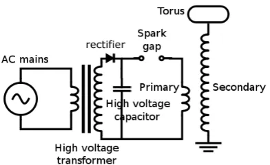
[image:18.612.234.430.326.446.2]He claimed that can transfer electrical energy at 95% efficiency, but he technology had to be shelved because the effects of transmitting such high voltages in electric arcs would have been disastrous to human and electrical vicinity [1]. Tesla theories of the wireless transmission of energy were a little different than today’s vision. It was centered on his consideration of the earth as a giant conductor. Tesla transferred energy directly through the earth’s surface [2].
Figure 1.1.1: Basic configuration of Tesla coil.
4
circuits will be in resonance. The voltage rises to such high levels that it is discharged through the discharge terminal in the form of an electric arc [1].
1.1.2 MIT Scientist
In 2007, for the first time after almost 120 years, a group of scientist from the Massachusetts Institute of Technology (MIT) led by professor Marin Soljacic had a breakthrough in the principle of wireless energy transfer and carried out a middle distance wireless energy transfer by resonance coupling of electromagnetism, where its efficiency was about 40%[8]. By using electrodynamics induction, they successfully wirelessly powered a 60W light bulb from a distance of 2 meters.MIT researchers has proposed a high frequency more than 10MHz scheme based on strongly coupled resonance for medium range and non radiative wireless energy transfer. The scheme which is considered to be non-radiative and anti-jamming could achieve a medium range wireless energy transfer. They investigated the range and rate of coupling and the interference of extraneous objects in the view of magnetic field coupling [3].
1.2 Problem Statement
5
third problem of statement is high cost of wiring and maintenance. With wireless energy transfer model, the wiring system at homes or offices also can be reduces.
Wireless transfer energy is an intimidating task because few people have ever been able to perform it efficiently at longer distance and then only with a very low amount of power. Even though there are many applications that would benefit from the ability to transfer energy wirelessly such as the charging of laptop personal computers and cell phones, but the theories about the wireless energy transfer are still very little and studies about it are only from physics. So, this prototype is important to show and demonstrate the concept of the wireless energy transfer to the public hopefully the appropriate technology will be developed from time to time to satisfy these applications.
1.3 Objective
This report proposes a wireless energy transfer prototype that is targeted at delivering enough power to light up a 3V of LED. It was used as the target for the amount of energy needed at the receiving coil. This project is a starter idea for the next consumer products after this. So, at the beginning of this project, we only focus on the production of prototype models to help people to more understand about the concept of wireless energy transfer. The objective of this study is first to investigate the principle of the electrical energy transmission, efficiency optimizing the structure and parameters, and determining the controlling method.The second objectives is to build a prototype model that can delivered electrical to light up a 3V LED receiver wirelessly.
1.4 Scope of Work
6
energy is because it non radiative and have the big potential to be apply to the electronic consumer.
The scope that covered in this project is only on hardware. For the aspects of hardware it consists of a transmitter, a handmade air core inductor which acts as an electromagnetic resonator and a receiver, another copper coil of similar dimensions to which the 3V LED to be powered is attached. We use 12V transformer to step down voltage from 240V to 12V. We will supply 12V AC to make the coil to oscillate and produce magnetic field. It also will connect to function generator to supply high frequency to transmitter. We will analyze the parameter based on frequency and distance. Means, from the prototype model we will show how the distance will affect the transferring of electrical energy transmitter to receiver.
1.5 Methodology
The prototype of WET consists of AC voltage power supply, 12V step down transformer, capacitor, transmitter and receiver inductor and 3V BLUE LED. To design the prototype, it all starts with the transmitter coil. From our calculation, the transmitter coil needs to create 126.4 KHz square wave AC signal. The secondary coil must have the same frequency because the wireless energy transfer system operates at resonance frequency. Thus, we start to build inductor by using a plastic circular coil former and enameled cooper wire. The construction of handmade inductor must be doing with carefully because it is very sensitive. It is to make sure that we get the accurate value of inductance. If we do not get the actual value of inductance, it is difficult to us to setup the proper frequency which enables to transfer electrical energy wirelessly.
7
LC oscillator. Resonance of a circuit relating capacitors and inductors occurs because the collapsing magnetic field of the inductor generates an electric current in its windings that charges the capacitor, and then the discharging capacitor provides an electric current that builds the magnetic field in the inductor, and the process is repeated continuously. The overall process will be explained more detailed in chapter 3.
1.6 Thesis Outline
The remainder of this thesis is organized as follows:
Chapter 2, Theoretical Review, in this part, we will describe in detail the concept of electromagnetic involved in the design of wireless energy transfer model. This is will help us to more understand how the wireless energy transfer works.
Chapter 3, Literature Review, analyzes the history of wireless energy transfer. This chapter considers historical references to wireless energy transfer as well as an analysis of the contemporary works dealing with the subject. In this part, we will analysis the others method of transferring energy as comparison to the method that we use. It also considers issues and concerns related to wireless energy transfer.
Chapter 4, Research Methodologies, shows the experimental procedure that was made in order to build the prototype system. Each component of the prototype is discussed and will be explain detailed.
Chapter 5, Result and Discussion, shows the result that was performed in order to verify the prototype was working properly. These chapters also will shows how the system performed in the various wireless energy transmission trials that were performed. It also will discuss and analyze the result that we get from the experiment.
8
CHAPTER 2
THEORETICAL REVIEW
2.0 Understanding the Concept of Electromagnetic Inductive Coupling.
In this part, we will describe in detail the concept of electromagnetic involved in the design of wireless energy transfer model. This is will help us to more understand how the wireless energy transfer works.
2.1 Concept of Electromagnetism
Magnetism is a basic force of nature that causes certain types of material to attract or repel each other. Permanent magnet is an example of objects having stable magnetic fields. Oscillating magnetic fields diverge with time, and can be supplied by alternating current flowing on a wire. The strength, direction, and level of magnetic fields are regularly visualized by drawings of the magnetic field lines.
9
simply different aspects of electromagnetism, and therefore are basically related. Thus, a changing electric field generates a magnetic field and on the other hand a changing magnetic field generates an electric field. This effect is called electromagnetic induction, and is the starting point of operation for wireless energy transfer system
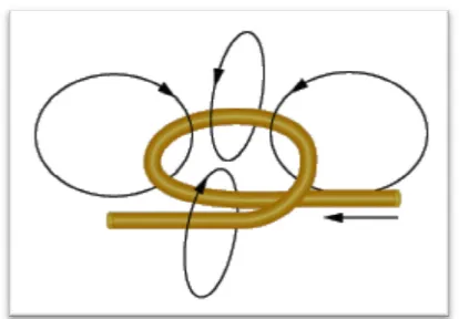
[image:24.612.222.429.317.461.2]The figure 2.1.1 below shows the form of the magnetic field around the wire. A circular magnetic field develops around the wire. The field generated is perpendicular to the wire and that the field's direction depends on which direction the current is flowing in the wire. Because the magnetic field around a wire is circular and perpendicular to the wire, an easy way to increase magnetic field is to coil the wire.
Figure 2.1.1 The magnetic field around wire.
For example, if you wrap your wire around a nail, connect the wire to the battery and bring one end of the nail close to the compass, we will find that it has a much larger effect on the compass. In fact, the nail behave just like a bar magnet.