58 (2012) 21–25 | www.jurnalteknologi.utm.my | eISSN 2180–3722 | ISSN 0127–9696
Full paper
Teknologi
Mechanical
Design
and
Analysis
of
All
‐
terrain
Mobile
Robot
Chee Fai Tana,b, Eng Sia Nga, Abdul Talib Dina*
a
Faculty of Mechanical Engineering, Universiti Teknikal Malaysia Melaka, Durian Tunggal Melaka, Malaysia b
Department of Industrial Design, Technical University Eindhoven, Eindhoven the Netherlands
*Corresponding author: [email protected]
Article history
Received: 12 January 2009 Received in revised form: 6 January 2011
Accepted: 2 April 2012
Graphical abstract
Abstract
This paper presents the conceptual mechanical analysis of the all-terrain mobile robot (AMoBo). The locomotion concept for all-terrain mobile robot is based on six independent motorized wheels. The mobile robot has a steering wheel in the front and the rear, and two wheels arranged on a bogie on each side. The front wheel has a spring suspension to guarantee optimal ground contact of all wheels at any time. The steering of the vehicle is realized by synchronizing the steering of the front and rear wheels and the speed difference of the bogie wheels. A prototype AMoBo was designed and fabricated. The developed prototype is about 66 cm in length and 23 cm in height. Testing size results show that the prototype able to overcome obstacles of same height as its wheel diameter and can climb stairs with step height of over 10 cm. Finite element analysis was used to analyse and verify the strength of each critical part of AMoBo. The base plate appeared to be the critical part with the highest shear stress and the lowest safety factor.
Keywords: All-terrain mobile robot; mechanical, design; analysis
Abstrak
Kertaskerja ini membincangkan analisis mekanikal bagi robot mobil semua medan (AMoBo). Konsep gerak alih untuk robot mobil semua medan adalah berdasarkan kepada enam roda yang bermotor. Kenderaan tersebut mempunyai roda kemudi di bahagian hadapan dan belakang, dan dua roda yang diaturkan sebagai bogi di kedua-dua belah. Roda hadapan mempunyai suspensi pegas untuk memastikan sentuhan permukaan yang optimal di setiap roda pada sebarang masa. Kemudi kenderaan diselaraskan dengan kemudi hadapan dan belakang dan juga perbezaan kelajuan pada roda bogie. Prototaip telah direka bentuk dan dihasilkan. Kenderaan yang dibangunakan berukuran sekitar 66 cm panjang dan 23 cm tinggi. Keputusan saiz ujian menunjukkan bahawa ia berupaya mengatasi halangan yang mempunyai ketinggian yang sama dengan diameter rodanya dan mampu memanjat tangga yang mempunyai ketinggian yang melebihi 10 cm. Analisis elemen terhingga telah digunakan untuk menganalisis dan mengesahkan kekuatan setiap bahagian yang kritikal pada AMoBo. Pinggan dasar adalah bahagian kritikal yang mempunyai tegangan ricih yang paling tinggi dan nilai faktor keselamatan yang paling rendah.
Kata kunci: Robot mobil semua medan; mekanikal; reka bentuk; analisis
© 2012 Penerbit UTM Press. All rights reserved.
1.0 INTRODUCTION
All-terrain mobile robot (AMoBo)is a remotely piloted or self-piloted vehicle that can carry cameras, sensors, communications equipment and other payloads. All terrain mobile robot is also known as all-terrain utilities, side-by-side vehicles or multi-terrain utilities’. The main requirement for AMoBo emerges from the task to do the dirty, dangerous and dull jobs. An AMoBo consists of a mobile, rigid chassis that can be equipped with functional heads for different terrain and various maintenance tasks. Such a platform is connected via a cable to an over ground surveillance unit. The cable supplies the AMoBo
performance. A good distribution of wheel speeds and torques is necessary to fulfill this goal. A good overview of physics-based control and terrain modeling techniques is presented in [2-8]. Moore et al. [9] designed a hexapod mobile robot with compliant legs and only six actuated degrees of freedom. Its ability to traverse highly fractured and unstable terrain, as well ascend and descend a particular flight of stairs. The robot, namely RHex, is reliable to climb a wide range of regular, full-size stairs with no operator input during stair climbing. Siegwart
et al. [10] developed a robot, measuring only about 60 cm in length and 20 cm in height, is able to passively overcome obstacles of up to two times its wheel diameter and can climb stairs with steps of over 20 cm. Based on a parallel architecture allowing for high ground clearance and excellent stability, the vehicle is able to passively overcome steps of twice its wheel diameter, to climb or to move in very rough terrain. The Journey Robot is an outdoor robot designed to run off road in unstructured environments. It was inspired by the Defense Advanced Research Projects Agency (DARPA) Grand Challenge and built as a prototype vehicle for that competition. Journey Robot is a fully autonomous, self-guided, mobile robot, capable of navigating on its own to an arbitrary set of waypoints while avoiding obstacles along the way [11]. Subsequently, an omnidirectional mobile robot is designed to move in any planar direction regardless of current pose. The robot able to navigate fast and robustly through cluttered urban environments and over rough terrain, due to their ability to track near-arbitrary motion profiles [12]. Carnegie and Cordes [13] designed and contructed a low cost caterpillar-track robot intended for outdoor use in a variety of irregular terrains. The resulting vehicle can carry a payload of 100 kg, can operate for a period of at least 1 hour and is reasonably immune to variations in weather or ground conditions. The robot is equipped with sufficient processing power and sensors to become capable eventually of autonomously completing assigned tasks.
The aim of the paper is divided into two sections. First, it presents the conceptual mechanical design of developed all-terrain mobile robot. Secondly, it discusses the mechanical design analysis of AMOBO such as kinematic motion and finite element analysis.
2.0 THE CONCEPTUAL MECHANICAL DESIGN
OF AMOBO
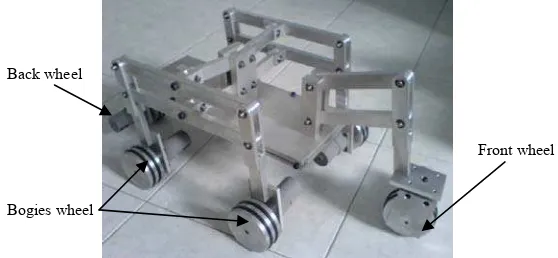
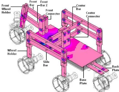
The developed conceptual AMoBo is a mobile vehicle that has six independent powered wheels as shown in Figure 1. In the front, the wheel is effectively in the same plane with its position governed by a linkage and a spring. The front wheel is act as the steering that used to guide the forward action of AMoBo. On both side, two wheeled bogies provide lateral stability of AMoBo. The position of the parallel-linkage bogie is passively articulated from reaction of the terrain. The back wheel is rigidly attached to the body. Subsequently, the back wheel also acts as steering to guide and support the movement of AMoBo. Figure 2 shows the side view of the AMoBo.
The parallel architecture of the bogies and the spring suspended fork provide a non-hyperstatic configuration for the six motorized wheels while maintaining a high ground clearance. This insures maximum stability and adaptability as well as excellent climbing abilities. The robot is designed to keep all its six motorized wheels in contact with the ground on a convex ground up to a minimal radius of 30 cm and on a concave ground up to a minimal radius of 35 cm. Figure 3 shows the vehicle at concave and convex ground.
Figure 1 The mechanical structure of AMoBo
Figure 2 The conceptual AMoBo from side view
(a) (b)
Figure 3 AMoBo at (a) concave and (b) convex ground
All six independent DC-motors integrated in the wheels have a power of 0.78 W each and can be controlled individually. The total weight of the robot base is 6 kg including 600 g for the battery (12 V, 2 Ah). Torque = 125 Nm, 60 rpm. From the torque and speed of motor, the velocity and the force that act on each wheel of terrain rover as follows:
V = πdN
60
= π (80 × 10-3) (60) 60
= 0.25132 m/s
Where,
V = velocity (m/s) d = diameter of wheel (m) N = rotation per minute (rpm)
P = F × V
0.78 = F × 0.25132
F = 3.1035 N
Where,
F = force (N)
P = power of DC motor (W) V = velocity (m/s)
Front wheel Back wheel
Bogies wheel
Front wheel (Steering)
Bogies wheel
3.0 DESIGN ANALYSIS
The design analysis is to validate the all-terrain mobile robot. There are two analysis discussed in this section, which are kinematics motion and finite element analysis (FEA) of critical parts.
3.1 Kinematic Motion
The all-terrain mobile robot is designed to travel at different terrain, where step-climbing process is one of the obstacle that this terrain vehicle able to overcome. A step-climbing sequence depicted in Figure 4 show the capabilities of AMoBo. The kinematics motion of terrain vehicle is analyzed by Autodesk Mechanical Desktop software.
Figure 4 Sequences showing the rover climbing a step
(height is same as the wheel diameter)
The goal of the flexibility terrain rover was to passively overcome a step same as the wheel diameter. Figure 4 and 5 depict a motion sequence of the robot climbing a step. First, the front fork gets on the step (Figure 4b and 5a). This relieves the load on the bogie wheels and thus eases the bogie to climb (Figure 4c and 5b). When the second bogie wheel is in contact with the wall, the bogie turns around the upper corner of the step. At this time, the centre of gravity almost reached its final height (Figure 4d and 5d). Finally, the last wheel can easily get on the step, dragged by the other five wheels. As the two bogies are independent from each other, it is even possible to climb the step if the robot is not approaching perpendicularly or if only one bogie encounters a step.
(a) (b)
(c) (d)
Figure 5 Climbing sequences for a step of 11 cm high (height is same
as the wheel diameter)
3.2 Finite Analysis
The critical parts of this all terrain vehicle were analysis using the finite element method (FEM) to verify the strength of the each part. All the parts are manufactured by computer numerical control (CNC) machine. The loads have been applied to test the strength of each critical part. Figure 6 shows the finite element analysis of AMoBo critical parts with 200 N loads. In this section, the part with the highest maximum shear stress (base plate), second highest maximum shear stress (wheel holder) and the second lowest maximum shear stress (front wheel holder) is discussed.
Figure 6 Finite element analysis of AMoBo critical parts
3.2.1 Base Plate
The base plate was made of aluminum alloy 6061 which designed to place battery, and controller onto it. This part has the highest maximum shear stress among other critical parts of terrain vehicle. The maximum shear stress of this part is 3.47 MN/m2 at nodes of 1545. Figure 7 shows the FEA result of the design subjected after maximum load of 200 N.
3.2.2 Wheel Holder
Figure 7 Stress analysis of base plate
Figure 8 Stress analysis of Wheel Holder
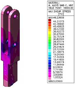
3.2.3 Front Wheel Holder
The front wheel holder was made of aluminum alloy 6061 which was designed to connect front bar with front wheel. The front wheel holder is the part which has the lowest maximum shear stress among all of the critical part of terrain vehicle. The maximum shear stress of this part is 319 KN/m2 which located at nodes of 635. Figure 9 shows the FEA result of the design load of 200 N apply onto it.
Figure 9 Stress analysis of Front wheel holder
The summary of the finite element analysis is listed in Table 1. The purpose of calculate the safety factor is to make sure that the part are safe to use at the certain force that act onto the part. From the analysis, the lowest safety factor for the critical part is 24. Subsequently, the highest safety factor of this terrain vehicle is 260. All of the safety factor for critical part is more than 3, hence, the conclusion can be state that this high flexibility multi terrain vehicle are safe to use in the condition of 200 N apply onto it.
Table 1 Property and safety factor of AMoBo
Part Material Mass
In the process of design analysis on the AMoBo structure, the critical parts need to be considered in order to function well in safe condition. Thus, all the critical parts of AMoBo were analysed by using the finite element method. The 200 N loads have been applied to test the strength of each of critical part. Table 2 show the maximum stress acted on the each part.
Table 2 Maximum stress on each part
Part Maximum Stress (N/m2)
Wheel Holder 1.22 × 10⁶
Centre Connecter 470 × 103
Centre Bar 405 × 103 Base Plate 3.47 × 10⁶
Back Holder 1.03 × 10⁶
Back Plate 552 × 103
471 × 103 N/m2 and 470 × 103 N/m2. After that, the parts of front connecter and centre connecter also have the high maximum stress. The value of both stress are 427 × 103 N/m2 and 405 × 103 N/m2. The lowest value for the critical part of the terrain vehicle is 319 × 103 N/m2 and 314 × 103 N/m2. The parts names are front wheel holder and front bar.
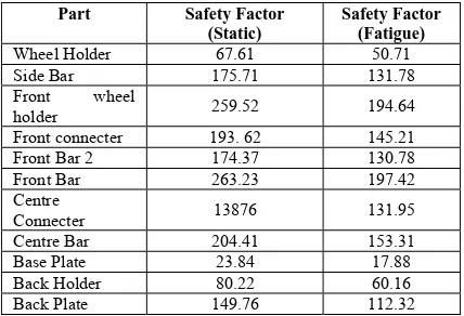
After the FEA and maximum stress data had been collected, the factor of safety for each part needs to be determined. The purpose of determination the safety factor for each part is to determine the safety the designed parts. In mechanical design, the minimum safety factor of one part is 3. Table 3 shows the safety factor for both static and fatigue analysis.
Table 3 Factor of safety for static and fatigue condition
Part Safety Factor
holder 259.52 194.64
Front connecter 193. 62 145.21 Front Bar 2 174.37 130.78 Front Bar 263.23 197.42 Centre
Connecter 13876 131.95
Centre Bar 204.41 153.31 Base Plate 23.84 17.88 Back Holder 80.22 60.16 Back Plate 149.76 112.32
The AMoBo is the mechanism that is move on the uneven terrain, thus, the analysis of fatigue safety factor is a need to make sure that every part of the terrain vehicle can perform well in fatigue condition. From data shown in graph and table, front bar is the part that has the highest safety factor which the static safety factor is 263.23 and fatigues safety factor is 197.42. However base plate is the part that has lowest safety factor among all the critical part where its static safety factor is 23.84 and the fatigues safety factor is 17.88. All the safety factor of the critical parts of terrain vehicle either static or fatigue is more then 3, this is showed that all designed part of this terrain vehicle are able to withstand the load of 200 N with safety situation.
5.0 CONCLUSION
The development of AMoBo is used to overcome the obstacle (step, stair and off-road) while moving. From the finite element analysis, some of the critical parts had been analysed and discussed. The developed AMoBo is able to withstand the 200 N external forces. The base plate appears to be the part has the highest maximum shear stress of 3.47 × 10⁶ N/m2. Subsequently, the base plate also the part with the lowest static safety factor of 23.84 and fatigue safety factor of 17.88. The base plate will be redesigned to lower the shear stress and increase the safety factor. The future recommendation for AMOBO is to improve the wheel by optimization method. The objective of optimization is to minimize the slip that is occurring. This can
be achieved by maximizing the traction forces, which is equivalent to minimizing the function of wheels. Next, it is recommended that the computed force and torque is applied to set a slip probability for each wheel. It is because the less pressure on the wheel, the more likely the wheel will slip. This is valuable information for probabilistic multi-sensor fusion. The knowledge of wheel-ground interaction is useful during the determination of wheel diameter changes that caused by tire compression. By adding sensors on the wheels, it can improve AMoBo from passive model to active model which can operate without human guide. Finally, the flexibility of the mechanical structure will be studied to increase the application in the future. Example of study that needs to be done on terrain rover is reduction of weight and design improvement at the wheel of terrain rover. The weight of terrain rover can be reduced by changing the material of wheel. Besides, study on the size of wheel also needed in order to improve the performance and ability of terrain rover to overcome the obstacle.
References
[1] Golombek, M. 1998. Mars Pathfinder Mission and Science Results.
Proceedings of the 29th Lunar and Planetary Science Conference. [2] Hung, M. H., D. E. Orin and K. J. Waldron. 2000. Efficient
Formulation of the Force Distribution Equations for General Tree-Structured Robotic Mechanisms with a Mobile Base. IEEE Transactions on Systems, man and Cybernetics, Part B: Cybernetics. 30(4): 529–538.
[3] Iagnemma, K., D. Golda, M. Spenko and S. Dubowsky. 2002. Experimental Study of High-Speed Rough-Terrain Mobile Robot Models for Reactive Behaviors. In Proceedings of the 8th International Symposium on Experimental Robotics, Sant'Angelo d'Ischia, Italy. [4] Iagnemma, K., H. Shibly, A. Rzepniewski and S. Dubowsky. 2001.
Planning and Control Algorithms for Enhanced Rough-Terrain Vehicle Mobility. In Proceedings of the Sixth International Symposium on Artificial Intelligence, Robotics and Automation in Space. Saint-Hubert, Quebec.
[5] Iagnemma, K., H. Shibley and S. Dubowsky. 2002. On-Line Terrain Parameter Estimation for Planetary Vehicles. In Proceedings of 2002 IEEE International Conference on Robotics and Automation (ICRA 2002). Washington D.C. 3142–3147.
[6] Iagnemma, K., and S. Dubowsky. 2000. Vehicle Wheel-Ground Contact Angle Estimation: with Application to Mobile Robot Traction Control. In Proceeding of 7th International Symposium on Advances in Robot Kinematics. Piran, Slovenia. 137–146.
[7] Cunningham, J., J. Roberts, P. Corke and H. Durrant-Whyte. 1998. Automation of Underground LHD and Truck Haulag. In Proceedings of Australian IMM Annual Conference. 241–246.
[8] Osborn, J.F. 1989. Applications of Robotics in Hazardous Waste Management. In Proceedings of the SME 1989 World Conference on Robotics Research. Gaithersburg, Maryland.
[9] Moore, E. Z., Campbell, D., Grimminger, F. and Buehler, M. 2002. Reliable Stair Climbing in the Simple Hexapod ‘RHex’. In Proceeding 2002 IEEE International Conference on Robotics and Automation. Washington DC. 2222–2227.
[10] Siegwart, R., Lamon, P., Estier, T., Lauria, M. and Piguet, R. 2002. Innovative design for Wheeled Locomotion in Rough Terrain. Robotics and Autonomous Systems. 40: 151–162.
[11] Anderson, D. P. and Hamilton, Mike. 2006. The Journey Robot. Dallas Personal Robotics Group.
[12] Udengaard, M., and Iagnemma, K. Design of an Omnidirectional Mobile Robot for Rough Terrain. In Proceedings of the 2008 IEEE International Conference on Robotics and Automation.