‘I hereby that I have read this dissertation and found its content and form to meet acceptable presentation standards of scholarly work for the award of
Bachelor of Mechanical Engineering (Thermal Fluid)’
Signature :………..
Name of Supervisor 1 :………..
CLAMPER POWERED BY PNEUMATIC SYSTEM
NORAZMIR BIN AMAT BASRI
This dissertation is submitted as partial fulfillment of the requirement for the degree of Bachelor of Mechanical Engineering (Thermal Fluid)
Fakulty of Mechanical Engineering Universiti Teknikal Malaysia Melaka
ii
DECLARATION
I hereby, declare this project entitled “Clamper Powered by Pneumatic System” is the result of my own research except as cited in the reference.
Signature :………..
Author’s Name :………..
iii
DEDICATION
For my beloved family,
iv
ACKNOLEDGEMENT
I would like to express my appreciation to all those who gave me the support to complete this project. I have to thank to my supervisor Mr. Suhaimi B. Misha, for his valuable suggestions and encouragement.
I am very appreciated and grateful to my entire friend who gave me information and idea for me to design this project.
Especially, I would to thank to my parent to give me support along the PSM 1 and PSM 2 and to enable me to complete this project.
v
ABSTRAK
vi
ABSTRACT
vii
CONTENT
CHAPTER TITLE PAGE
DECLARATION ii
DEDICATION iii
ACKNOWLEDGEMENT iv
ABSTRAK v
ABSTRACT vi
CONTENT vii
LIST OF FIGURES xi
LIST OF TABLES xiii
CHAPTER I INTRODUCTION 1
1.1 Introduction 1
1.2 Problem Statement 2
1.3 Objective 2
1.4 Scope 3
1.5 Pneumatic System 3
viii
CHAPTER TITLE PAGE
CHAPTER II LITERATURE REVIEW 6
2.1 Structure of Pneumatic Actuating System 6 2.2 Pneumatic Systems for Velocity Control 9 2.3 Pneumatic Systems for Force Control 10
2.4 Pneumatic Cylinders 12
2.5 Directional Valve Actuators 14
2.6 Pressure Regulator 14
2.7 Adjustment of Acting Force in Pneumatic
Actuators 16
2.8 Type of Clamper 18
2.8.1 Feather Hand Clamper 18 2.8.2 Fulcrum Hand Clamper 20 2.8.3 Parallel Style Wide Opening Clamper 21 2.9 Low cost using the electro pneumatics 23
CHAPTER III METHODOLOGY 24
3.1 Introduction 24
3.2 Flow Chart 25
3.3 Conceptual Sketching 26
3.4 Design Using SolidWorks Software 26 3.5 Cutting and Fabrication Process 29
3.5.1 Process of Cutting 29
ix
CHAPTER TITLE PAGE
3.7 Laboratory Testing and Analysis 32
3.8 Working procedure 33
3.9 Equipment and apparatus 40
3.9.1 Chop Saw 40
3.9.2 Shearing Machine 41
3.9.3 Table drill 42
3.9.4 Metal inert gas (MIG) 43
3.9.5 Hand Grinder 44
CHAPTER IV RESULT 45
4.1 Experiment Result 45
4.2 Data from Experiment 46
4.3 Graphs from the Experimental Results 53
CHAPTER V DISCUSSION AND ANALYSIS 56
CHAPTER VI CONCLUSION AND RECOMMENDATION 61
6.1 Conclusion 61
x
REFERENCES 63
BIBLIOGRAPHY 64
APPENDIX A 65
xi
LIST OF FIGURES
NO TITLE PAGE
1.0 Feather Hand Clamper 4
1.1 Fulcrum Hand Clamper 5
1.2 Parallel Style Wide Opening 5
2.0 Block Diagram of the Pneumatic Actuating System 6 2.1 Rotary Actuator with Magnetorheological Brake 9 2.2 Force Control Actuator with Pressure Regulator 11
2.3 Double Acting Pneumatic Cylinder 12
2.4 Pressure Regulator 16
2.5 Dynamic of the Open Loop Pneumatic Cylinder with
Constant Velocity Motion 17
2.6 Detail Drawing for Feather Hand Clamper 18 2.7 Graph Gripping Power (N) Versus Jaw Length (cm) 19 2.8 Detail Drawing for Fulcrum Hand Clamper 20 2.9 Graph Gripping Power (N) Versus Jaw Length (cm) 20 2.10 Detail Drawing for Parallel Wide Style Opening Clamper 22 2.11 Graph Gripping Force (N) Versus Gripping Point (mm) 22
2.12 The Effective Gripping Point (R) 22
xii
NO TITLE PAGE
3.2 Position of cylinders 28
3.3 MIG welding process 30
3.4 Body of the model 33
3.5 : Joining tire process 34
3.6 Joining process body and arm 34
3.7 Cover 35
3.8 Joining for assembling the cylinders 36 3.9 Joining process of the clamper and arm. 36
3.10 Flow control valve 37
3.11 5/3 way directional control valve. 37
3.12 Process of assembling tubing 38
3.13 Wiring process 38
3.14 Push button 39
3.15 The complete of the model 39
3.16 Chop saw with fiber disc 40
3.17 Shearing machine 41
3.18 Table drill 42
3.19 Metal inert gas (MIG) set. 43
3.20 Hand grinder or Angle grinder 44
4.0 Graph Time (s) versus weight (kg) 53
xiii
LIST OF TABLES
NO TITLE PAGE
4.1 Table of Time and Velocity for cylinder 1 (6 bar) 46 4.2 Table of Time and Velocity for cylinder 2 (6 bar) 47 4.3 Table of Time and Velocity for cylinder 1 (7 bar) 48 4.4 Table of Time and Velocity for cylinder 2 (7 bar) 49 4.5 Table of Time and Velocity for cylinder 1 (8 bar) 50 4.6 Table of Time and Velocity for cylinder 2 (8 bar) 51
4.7 Maximum weight (kg) for Clamper 52
5.1 Table for maximum weight (kg) and maximum
force (N) for cylinder1 58
5.2 Table for maximum weight (kg) and maximum
1
CHAPTER I
INTRODUCTION
1.0 Introduction
A clamper is a device to hold or secure objects tightly together to prevent movement or separation through the application of inward pressure. There are many types of clamper available for many different purposes. Some are temporary, as used to position components while fixing them together, others are intended to be permanent. Anything which performs the action of clamping may be called a clamper, so this gives rise to a wide variety of terms across many fields.
2
fabrication of the arm and the clamper holder. The characteristics of metal will be used for making the arm are angle bar mild steel 25.4mm X 25.4mm X 2mm. Type clamper will be used is parallel style wide opening air gripper. It is because it more powerful than other. The cylinder will be used is double acting cylinder and also 5/3 way directional control valve. For make the motion smooth, flow control valve will used to reduce the velocity movement of the cylinder.
1.1 Problem Statement
The cost of the hydraulic system is very expensive. In this project, pneumatic system will be used to reduce the cost. The hydraulic system is very suitable for high force needed and heavier component but it not suitable for little and light component. The pneumatic system is very suitable for clamp product because the force of pneumatic system is lower. The surface of the product or component will not damage. The maximum load can be hold by the pneumatic clamper will be done by the experiment. However, the pneumatic system only can use in low range of pressure application.
1.2 Objective
1) To design and fabricate the clamper powered by pneumatic system. 2) To analyze the capability of the pneumatic clamper motion.
3
1.3 Scope
This project is about the designing and fabricating the pneumatic clamper. For this project, the selection of clamper is very important. Basically, the concept of the system is referring to excavator system. After the fabrication, the analysis and testing will be run to analyze the system capability. The experiment will determine the maximum load that can be raised by the system.
1.4 Pneumatic System
The pneumatic actuating servo systems used in automatic devices have two major parts: the power and control subsystems.
4
The important part of the control subsystem is the command module (or task controller), which stores the input information (such as desired positioning points, trajectory tracking, velocity, or force value) and selects them via input combinations.
For example, in the positioning actuator, the positions can be stored in the command module (as position list records), and moves command can include additional parameters such as velocity and acceleration. In this case, to improve the control performance, an adaptive control system with the controller adjusted bases on the identification results of the plant can be used.
1.5 Type of Clamper
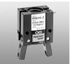
[image:18.612.272.385.491.595.2]For this project, 3 type of clamper will be discussed: feather hand, fulcrum hand and parallel style wide opening.
Figure 1.0 : Feather hand clamper ( Source www.ckd.com)
5
Figure 1.1 : Fulcrum hand clamper (Source www.ckd.com)
The Fulcrum hand clamper will produce force about 8 N with the maximum length of jaw. The mass of this clamper is 90 g and the bore size is 15 mm.
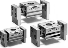
Figure 1.2 : Parallel style wide opening (Source www.ckd.com)
[image:19.612.269.388.304.387.2]6
CHAPTER II
LITERATURE REVIEW
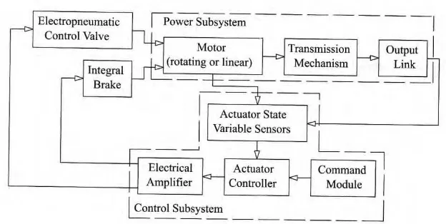
2.1 Structure of Pneumatic Actuating System
[image:20.612.172.484.449.606.2]The pneumatic actuating servo systems used in automatic devices have two major part: the power and control subsystems (Figure 2).
7
The main part of the power subsystem is the motor, which may be of the rotating or linear type. Basically, this device converts pneumatic power into the useful mechanical work or motion. The linear motion system widely uses the pneumatic cylinder, which has two major configurations: single or double action. For the single action configuration, the cylinder can exert controllable forces in only one direction and uses a spring to return the piston to the unenergized position. A double acting actuator can be actively controlled in two directions. In the case the of rotary actuation, the power unit is a set of vanes attached to a drive shaft and encased in a chamber. Within the chamber, the actuator rotates by differential pressure across the vanes and the action transmits through the drive shaft.
Most often, the pneumatic actuator has the direct-drive structure; that is the output motor shaft or rod is the actuator output link. However, sometimes the transmission mechanisms are installed after the motor; in this case, the output shaft is the actuator output link (e.g., in the rotating actuator where the pneumatic cylinder is used as the motor).
Actuator state variable sensors are the input elements of the control subsystems. In general, the displacement, velocity, acceleration, force, moment, and pressure can be measured in the pneumatic actuator. Different sensor designs can read incrementally or absolutely; they can contact a sensed object or operate without contact; and they span a board range of performance and pricing levels. Linear position sensors are widely used as feedback elements for motion control in pneumatic actuating systems; there are precision linear potentiometers, linear variable differential transformers (LVDTs), magneto-strictive sensors, and digital optical or magnetic encoders.
8
The central element of the control subsystem is the controller, which provides control, processing, comparing, and diagnostic functions. In general, the controller may be of both types: analog and digital. Currently, more than 90% of all controllers in industry are of the digital type. The main role of this device is to form control signal according to the control algorithm. The most common form of process controller used industrially is the PID (proportional + integral + derivative) controller. PID control is an effective method in cases where the plant is expressed as a linear model, and the plant parameters do not change with wide or prolonged use. Owing to the compressibility characteristic of the air and high friction force, the pneumatic actuator system is very highly nonlinear, and the system parameters are time variant with changes in the environment. There are main causes, which are limited application of PID control in the pneumatic actuator systems.
For pneumatic actuators, the most common and successful controller is the so-called state controller or PVA (position, velocity, acceleration) controller. In this case, the control signal is a function not only of the positioning signal, but also of the velocity and acceleration signal of the output link motion (for the positioning actuator).
As noted above, in pneumatic actuator, the dynamic of the plant change during performance. In this case, to improve the control performance, an adaptive control system with the controller adjusted bases on the identification results of the plant can be used.
9
2.2 Pneumatic Systems for Velocity Control
The application fields of servo pneumatic actuators with speed motion control include arc welding machines; painting and printing; scanning motion systems in inspection devices; cutting machines for plastic, wood and the fabric materials; gluing; and others.
practice, open loop pneumatic actuators are seldom used in these applications because of the poor ability to maintain constant velocity stabilization owing to low internal damping, high sensitivity to load and friction force changes, as well as the actuator’s nonlinear characteristics.
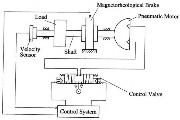
[image:23.612.177.481.436.639.2]pneumatic actuator with magnetorheological braking devices can also be used in velocity control systems. For example, the linear system with a pneumatic cylinder of 32 mm diameter bore and 160 mm stroke has the ability to move with constant velocity from 20 to 500 mm/s. In this case, the control accuracy is about 10 % of the programmed value.
10
Figure 2.1 is a schematic diagram of the rotary pneumatic actuator, which has the ability to control the rotation velocity. The function of the three position solenoid control valve is to ensure that the motor is rotated in the desired direction (clockwise or counterclockwise). The motor is stopped when the valve is at the center position. The actuator rotates the shaft, on which the magnetorheological brake, load, and velocity sensor are installed. Changing the brake impedance torque control the shaft’s angular velocity. For this system, the control accuracy is about 15% of the programmed value.
A pneumatic actuator for velocity control with a servo or proportional valve is based on the same principle of error signal generation as the positioning servo actuator, expect that the velocity of the output is sensed rather than position of the load. When the velocity loop is at correspondence, an error signal is still present and the load moves at the desired velocity.
Most pneumatic servo applications require position control in addition to velocity control. The most common way to provide position control is to add a position loop “outside” the velocity loop, which is known as cascading loop. In this case, the position error is scaled by the position loop gain to produce the velocity command.