Master of Electrical Engineering (Industrial Power)
Faculty of Electrical Engineering
IMPLEMENTATION OF p-q THEORY ON UNIFIED
POWER FLOW CONTROLLER
Haryani binti Hassan
ii
IMPLEMENTATION OF p-q THEORY ON UNIFIED POWER FLOW CONTROLLER
HARYANI BINTI HASSAN
A dissertation submitted
In partial fulfillment of the requirements for the degree of Master of Electrical Engineering (Industrial Power)
Faculty of Electrical Engineering
UNIVERSITI TEKNIKAL MALAYSIA MELAKA
i
ABSTRACT
iii
Haryani Binti Hassan DECLARATION
I declare that this dissertation entitle “Implementation of p-q Theory on Unified Power Flow Controller” is the result of my own research except as cited in the references. The dissertation has not been accepted for any degree and is not concurrently submitted in the candidature of any other degree.
iv APPROVAL
I hereby declare that I have read this dissertation and in my opinion, this dissertation is sufficient in terms of scope and quality as a partial fulfillment of Master of Electrical Engineering (Industrial Power).
Signature :………. ... Supervisor Name :… ……… ... Date :……….. ...
DEDICATION
To:
my beloved husband Mohd Azrin bin Abu Bakar
my children Nur Hazwani, Mohd Haziq, Nur Haziqah, Nur Hazirah and Muhammad Hazali
my late father Hassan bin Abdullah my mother Halimah binti Ismail
ii ABSTRAK
iii
ACKNOWLEDGEMENT
I would like to express my gratitude to Allah by His permission I can finish my project successfully. Alhamdulillah, His Willingness has made it possible for me as the author to accomplish my research.
Special thanks dedicated to my supervisor Prof. Madya. Dr. Ismadi Bugis for guiding this research at every stage with clarity, spending much time discussing and help with this research, and that priceless gift of getting done by sharing his valuable ideas as well as his knowledge.
I am very greatly indebted to the Department of Electrical Engineering, University Technical Malaysia Melaka for giving me the opportunity to pursue my Masters of Electrical Engineering (Industrial Power).
I also want to show my gratefulness to the Ministry of Higher Education on the financial support through the scholarship and privileges provided in the HLP program for furthering my study in master level.
iv
1.2 Introduction to Power Flow Control 3
1.3 Introduction to FACTS 5
1.3.1. Group of conventional thyristor controlled FACTS devices 7 1.3.1.1 Static Var Compensator (SVC) 8 1.3.1.2 Thyristor Controlled Series (TCSC) 9 1.3.1.3 Thyristor Controlled Phase Shifter (TCPS) 9 1.3.2. Group of voltage source converter based FACTS devices 10
1.3.2.1 Statistic Synchronous Compensator (STATCOM) 11 1.3.2.2 Static Synchronous Series Compensator (SSC) 12 1.3.2.3 Unified Power Flow Controller (UPFC) 13
1.4 Introduction to p-q Theory 14
1.5 Problem Statement 15
v
3.2 UPFC Configuration and Principles of Operation 30
vi
5.4 Result 79
5.4.1 First Case: Changing the Pref and Qref constant 85 5.4.2 Second Case: Changing the Qref and the Pref Constant 87 5.4.3 Third Case: Changing the Pref and Qref 89 5.5 UPFC in 132 KV Transmission Line 91 5.6 Conclusion of Result and Discussion 98
6. CONCLUSION 100
6.1 Introduction 100
6.2 Research Summary 100
6.3 Objective Achievements 101
6.4 Future Work 102
6.5 Contribution of Research 103
6.6 Conclusion 103
REFERENCES 106
vii
LIST OF TABLES
TABLE TITLE PAGE
1.1 Summary of Different FACTS Controllers 6
5.1 Simple Transmission System Parameters 60
5.2 Simulation System Parameters for 415V 73
viii
LIST OF FIGURES
FIGURE TITLE PAGE
1.1 Interconnection between two synchronous systems 3 1.2 Phasor Diagram for The Interconnection of Figure 1.1 4 1.3 Group of conventional thyristor controlled FACTS devices 7
1.4 Schematic Diagram of SVC 8
1.5 Schematic Diagram of TCSC 9
1.6 The configuration of TCPS 10
1.7 Group of VSC based FACTS device 11
1.8 Schematic Diagram of STATCOM 12
1.9 Schematic Diagram of SSSC 13
1.10 Schematic Diagram of UPFC and its Phasor Diagram 14 2.1 Control algorithm for extraction of compensation currents 21 2.2 The control block diagram of generator side converter using
d-q Theory 23
2.3 The control block diagram of generator side converter using
p-q Theory 24
2.4 Shunt inverter controller with additional PI 26 2.5 Series inverter controller with additional PI 27
ix
3.2 Simplified configuration and phasor diagram of UPFC 33
3.3 Voltage control mode 34
3.4 Voltage injection mode 35
3.5 Phase Angle Regulation Mode 36
3.6 Power Flow Control Mode 37
x
5.6 Voltage at the injected, sending and receiving end when °
5.9 Voltage at the injected, sending and receiving end when ° 5.18 The result of reactive power when the reference is 4500Var 80 5.19 Parameter value for PI gain controller of active power 81 5.20 Parameter value for PI gain controller of reactive power 82 5.21 The result of active power after calculating the PI controller 84 5.22 The result of reactive power after calculating the PI controller 85
5.23 Active power output for first case 86
xi
5.27 The sending end voltage, DC voltage and the output power
for third case 90
5.28 Thermal and stability limit versus line length 91
5.29 132KV power system without UPFC 94
5.30 Active and reactive power without UPFC 95
5.31 132KV power system with UPFC 96
5.32 Active and reactive power with UPFC 97 5.33 Active and reactive power during the different time load added 98 6.1 Automatic power flow control mode for SSSC 101 6.2 Automatic voltage control mode for STATCOM 102
6.3 Fuzzy direct controller 102
xii
LIST OF APPENDICES
APPENDIX TITLE PAGE
A PI Controller Gain Calculation 114
B Simulink Model for Vabc to Vαβ Conversion 117
C Simulink Model for Iabc to Iαβ Conversion 118
D Signal Builder Parameters of Pref and Qref 119
xiii
LIST OF ABBREVIATIONS
d-q Theory - Instantaneous Current Component Theory ET - Excitation Transformer
FACTS - Flexible Alternating Current Transmission System HV - High voltage
Ki - Integral Gain Kp - Proportional Gain PI - Proportional Integral
p-q Theory - Instantaneous Power Theory PWM - Pulse Width Modulation
SSSC - Static Synchronous Series Compensator SIL - Surge Impedance Loading
STATCOM - Static Synchronous Compensator SVC - Static Var Compensator
TCPS - Thyristor Controlled Phase Shifter TCR - Thyristor-controlled reactor
TCSC - Thyristor Controlled Series Compensator THD - Total Harmonic Distortion
xiv
LIST OF PUBLICATION
1 CHAPTER 1
INTRODUCTION
1.1 General Introduction
2
Flexible Alternating Current Transmission System (FACTS) is the alternative option that can be used to control the power flow in an existing transmission line. This idea was introduced by Hingorani in the late 1980’s (Hingorani, 2000). The intention to use the FACTS is to enhance the controllability as well as the power transfer capability of a transmission line by using a power electronic switching device to replace the traditional way. As a result, it will help the existing transmission lines such that able to transfer higher power capacity without undermining the stability and security by controlling the main parameters that affect the power flows in a transmission line. Voltage, impedance and phase angle are the parameters that influence the power flows in a transmission line.
One of the most versatile FACTS is Unified Power Flow Controller (UPFC) that popularized by Gyugyi in 1991 (Akagi, 2007). UPFC is the combination of shunt and series controller that is used to control either selectively or simultaneously all the three parameters to influence the power flow in a transmission line. In this dissertation the UPFC will be specifically discussed in the implementation of the instantaneous active and reactive power theory to control the transmission line parameters.
3
Propotional Integral (PI) Controller. Moreover the presentation of mathematical equation of p-q Theory will be shown in matrix form.
1.2 Introduction to Power Flow Control
Electric power flow initially is the result of the interaction between power generation, transmission and distribution. This led to the interest in research of power flow control technology, which had increased since last several years.
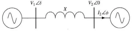
The principle of power flow over a transmission line can be simplified as in Figure
1.1 where V1 is the magnitudes of the sending end voltage and V2 is the magnitude of the
receiving end voltage. By ignoring the resistance and capacitance, the transmission line assumed to have purely inductive impedance, X which interconnects between the two end busses.
Figure 1.1: Interconnection between two synchronous systems (Arillaga, 2007)
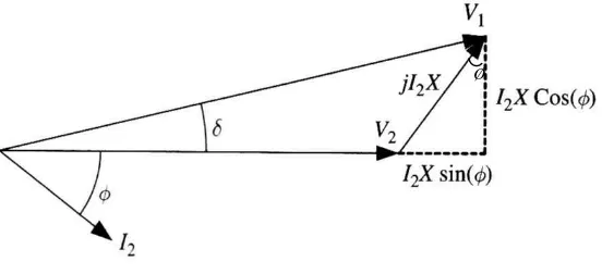
Assume that the voltage V2 as the phase reference meanwhile the voltage V1 leads
the V2 by δ angle and the current I2 lags its voltage by ∅ angle as shown in Figure 1.2,
these expressions can be derived (Arillaga, 2007):
4
Figure 1.2: Phasor Diagram for The Interconnection of Figure 1.1 (Arrillaga, 2007)
From Equations (1.1) and (1.2) the active and reactive powers become:
δ
Equations (1.3) and (1.4) show that the power flow through the transmission line can be
controlled by varying one or more of these parameters V1, V2, δ and X. Even though the
generated voltage phase and magnitude values can be controlled by the turbine governor and the generator, the controls are very slow and inefficient which tend to have stability problems. FACTS is the device that can overcome this problem.
5 1.3 Introduction to FACTS
FACTS controllers use power electronics to set control for one or more transmission parameters that can increase power transfer capability. It can be categorized in two classifications either based on their connection in transmission system or based on the power electronics used in the system.
1. Classification which according to the connection of the devices within the transmission system can be divided into three connections:
a) Shunt connection b) Series connection c) Combine connection
2. Classification based upon the power electronics used in the control system or the operational concepts, which can be divided in two groups namely:
a) Group of conventional thyristor based controller