AUTOMATIC POWER FACTOR FOR RESIDENTIAL
MOHD GHAFFAR BIN GHAZI
BEKE
“I hereby declare that I have read this report and in my opinion this report in term of content and quality requirement fulfils the purpose for the conferring of the Degree of Bachelor in Electrical Engineering.”
Signature :
Name of Supervisor : MR. AMINUDIN BIN AMAN
AUTOMATIC POWER FACTOR FOR RESIDENTIAL
MOHD GHAFFAR BIN GHAZI
This Report Is Submitted In Partial Fulfillment Of Requirements For The Degree
Of Bachelor In Electrical Engineering
(Power Electronic and Drives)
Faculty of Electrical Engineering
Universiti Teknikal Malaysia Melaka (UTeM)
“I hereby declare that this report is a result of my own work except for the excerpts that
have been clearly in the references”
Signature : ……….
Student : MOHD GHAFFAR BIN GHAZI
Specially dedicated to
My beloved father and mother… Ghazi bin Che Soh & Salmah Binti Talib
My beloved brother n sisters …
Ghadzali, Noridah, Irwan Faizal, Ilias and Shahidi,
My inspirational motivator…
All my friends,
ACKNOWLEDGEMENTS
First of all, I would like to express my thankfulness and gratitude to Allah S.W.T who has given me all the strength that I needed to complete this final year project and also prepare this report.
With this opportunity, I would like to express my gratitude to the Faculty of electrical Engineering (FKE), Universiti Teknikal Malaysia Melaka (UTeM) generally, and especially to my supervis or Mr. Aminudin Bin Aman for this help, advices and guidance that he gave during this project.
ABSTRACT
ABSTRAK
i
TABLE OF CONTENTS
CHAPTER TITLE PAGE
TITLE PAGE i vii
ADMISSION ii
DEDICATION iii
ACKNOWLEDGMENT iv
ABSTRACT v
ABSTRAK vi
TABLE OF CONTENTS vii
LIST OF TABLES ix
LIST OF FIGURES x
LIST OF ABREVIATION xiii
LIST OF APPENDICES xvi
1 INTRODUCTION
1.1 Introduction 1
1.2 Problem Statements 1
1.3 Objective Of Project 2
1.4 Scope Of Project 2
1.5 Project Report Outline 3
2 LITERATURE REVIEW
2.1 Introduction 5
2.2 Programming of PIC-Micro Controller for 6 Power Factor Correction
2.3 Power Factor Theory 7
2.4 Power Factor Correction Theory 8
3 METHODOLOGY
3.1 Introduction 22
3.2 Methodology flow chart 23
3.3 Explanation flow chart methodology 25
4 HARDWARE DEVELOPMENT
4.1 Introduction 26
4.2 Circuit Simulation 26
4.3 Microcontroller Program 32
4.4 The Development of the Project 41
5 RESULTS AND DISCUSSION
5.1 Introduction 46
5.2 Result And Discussion 46
5.3 Data Collection 57
6 CONCLUSION AND RECOMMENDATION
6.1 Conclusion 60
6.2 Recommendation 61
LIST OF REFERENCES 62
LIST OF TABLES
TABLE TITLE PAGE
ix
2.1 EX-OR 74HCT86 Truth Table 12
4.1 Output file 36
5.1 True Table Of EX-OR 74HCT86 47
5.2 Table Simulation Input voltage versus output voltage 53 5.3 Table Experimental Input voltage versus output voltage 54
LIST OF FIGURES
FIGURE TITLE PAGE
2.1 Overview of design system 6
2.2 Power Triangle 7
2.3 Uncorrected circuits 8
2.4 Power Triangle uncorrected circuit 9
2.5 Corrected circuits 9
2.6 Power Triangle after adding capacitor 10
2.7 Op-Amp LM741 symbol 11
2.8 Op-Amp LM741 Pin Connection 11
2.9 EX-OR 74HCT86 symbol 12
2.10 EX-OR 74HCT86 Pin Connection 13
2.11 LM339 Pin Connection 13
2.12 Transistor as switch 14
2.13 Output voltage vs primary current for LTS25-NP transducer 15 2.14 The different possibilities for connecting the 16
primary current circuit
2.15 An ideal step-down transformer showing magnetic flux in 17 the core
2.16 Transformer equivalent circuits 17
2.17 Full-wave rectification circuit and wave form 18
2.18 LM7805 19
2.19 Pin diagram of microcontroller 16F877A 20
3.1 Flow chart of methodology 23
4.0 Angle difference Schematic Circuit 27
4.1 Output Current Transducer LTS25 Circuit 28
4.2 AC/DC Rectifier Schematic Circuit 28
4.3 Switching Capacitor Circuit 29
4.4 Input PIC Schematic Circuit 30
4.6 Flow Chart Program 32
4.7 Continues Flow Chart Program 33
4.8 mikroC IDE Snapshoot 34
4.9 mikroC new build Project Snapshoot 35
4.10 Dialog box 36
4.11 Select PIC model Snapshoot 37
4.12 Setting in Option Snapshoot 37
4.13 Configure option Snapshoot 38
4.14 Configure Privileged instruction option Snapshoot 38
4.15 Load Hex file Snapshoot 39
4.16 Download program to PIC Snapshoot 39
4.17a Serial port cable 40
4.17b Programmer 40
4.18 The right pin state and toggle switch 40
4.19 Simulation circuit 42
4.20 PCB layout simulation circuit 43
4.21 Printed PCB layouts 44
4.22 UV expose process 44
4.23 PCB after develop process 45
4.24 Board after finishing etching process 45
5.1 Result Simulation Circuit Detection Angle Wave 47
5.2 Hardware Circuit Detection Angle Wave 48
5.2 a Output Wave Current Transducer 48
5.2 b Output Wave Voltage Transformer 49
5.2 c Output Wave Current Transducer After Composite 49 DC Component
5.2 d Output Wave Current Transducer After Amplified 50 Using Op-Amp 741
5.2 e Output Wave At Pin 1 Comparator 50
5.2 f Output Wave At Pin 2 Comparator 51
5.2 g Output Wave At Pin 3 EX-OR 74HCT86 51
5.3 AC/DC Rectifier Circuit Simulations 52
5.5 Result Simulation LED on Circuit PIC16F877A 55
5.6 Result recording House A 57
LIST OF ABBREVIATION
A Ampere xiii
ADC Analog To Digital
AC Alternating Current
DC Direct Current
C Capacitor
R Resistance
I Current
V Voltage
Hz Hertz
PFC Power Factor Correction
PF Power Factor
USB Universal Serial Cable
LIST OF APPENDICES
APPENDIX TITLE PAGE
A Microchip PIC16F877 Microcontroller 64
B Programming of PIC-Micro Controller for 69 Power Factor Correction
CHAPTER1
INTRODUCTION
1.1Introduction
This project is to improve power factor using capacitor and it switching controller control by microcontroller. Power factor is a ratio of the real power flowing to the load to the apparent power. By using this definition, power factor can be composite by using capacitor that gives reactive power to the load. In this project it consists four parts to archive before it successfully operate, that part are simulation circuit, programming, hardware development and testing.
1.2Problem statement
1.3 Objective of project.
These project automatic power factor corrections develop focuses on the following four objectives:
• To improve power efficiency by using PFC method. • To develop automatic trigger switching PFC.
• To develop real time improvement power efficiency device. • To reduce utility bill.
1.4 Scope of project.
This following four scope projects is guided to complete this project. There are:
• Residential using single phase 240V/50Hz. • Use below current 20A.
1.5 Project Report Outline
Generally this project report is divided into six chapters, where it consists:
Chapter 1: Introduction
Chapter 2: Literature Review Chapter 3: Methodology
Chapter 4: Hardware Development Chapter 5: Results and Discussions
Chapter 6: Conclusion and Recommendation
Chapter 1 is an introduction for this final report that provided brief what is all about Automatic power factor correction for residential. In this chapter problem statement and objective for this project are included to give the direction of this report are.
Chapter 2 introduce to literature review for this project, what theory and component that use for develop this project. Literature reviews are previous study in this project that can be used to guide and give improvement to the project. It gives the batter chance to success will to develop and innovation in this project. Theory and component are give a general knowledge about this project and it will use to develop on this project.
Chapter 3 introduce to methodology that used on this project and it give a surface guided how this project are build. All these steps are complete shows how all steps; start with research on literature review to get result worked from experiment in the lab.
Chapter 5 introduce to result and discussion for this project. Result that get form experiment and testing are compiled and it discuss in detail in this chapter. From result and discussion in this chapter it will give if this project successfully or not bases on data that get from experiment.
CHAPTER 2
LITERATURE REVIEW
2.1 Introduction
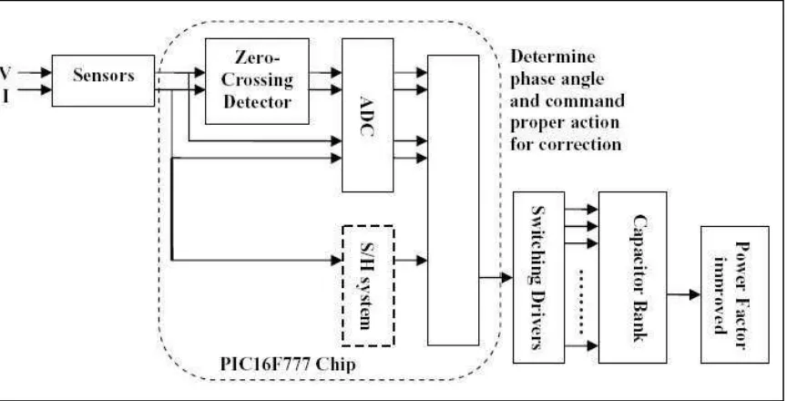
2.2 Programming of PIC-Micro Controller for Power Factor Correction.
[image:22.595.87.519.334.554.2]This part discussed about the intelligent Power Factor Correction (PFC) which focused on design and development of a three-phase power factor corrector using PIC (Programmable Interface Circuit) micro-controlling chip. This involves sensing and measuring the power factor value from the load using PIC and sensors. Then using proper algorithm to determine and trigger sufficient switching capacitors in order to compensate excessive reactive components, thus withdraw PF near to unity and as a result acquires higher efficiency and better quality AC output [1]. Figure 2.1 shows the typical arrangement power factor correction design using PIC.
2.3 Power Factor Theory.
Power factor is the ratio between the KW and the KVA drawn by an electrical load where the KW is the actual load power and the KVA is the apparent load power. It is a
measure of how effectively the current is being converted into useful work output and more particularly is a good indicator of the effect of the load current on the efficiency of the supply system.
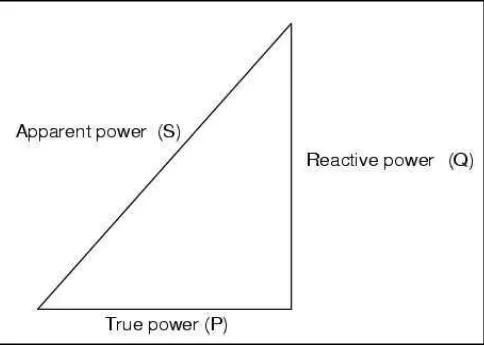
[image:23.595.194.436.447.620.2]All current will cause losses in the supply and distribution system. A load with a power factor of 1.0 result in the most efficient loading of the supply and a load with a PF of 0.5 will result in much higher losses in the supply system. A poor power factor can be the result of either a significant phase difference between the voltage and current at the load terminals, or it can be due to a high harmonic content or distorted/discontinuous current waveform. Poor load current phase angle is generally the result of an inductive load such as an induction motor, power transformer, lighting ballasts, welder or induction furnace. A poor PF due to an inductive load can be improved by the addition of power factor correction. Figure 2.2 shows clarified power triangle in electrical AC system.
From the power triangle, power can be calculate by this formula.
Real Power ( P ) = VI COS θ ( 2.00 )
Reactive Power ( Q ) = VI SIN θ ( 2.01 )
Apparent Power ( S ) = VI ( 2.02 )
Power Factor ( PF ) = COS θ ( 2.03)
2.4 Power Factor Correction Theory.
Power factor correction (PFC) is the process of adjusting the characteristics of electric loads in order to improve power factor so that it is closer to unity (1). Power factor correction may be applied either by an electrical power transmission utility to improve the stability and efficiency of the transmission network; or correction may be installed by individual electrical customers to reduce the costs charged to them by their electricity supplier. A high power factor is generally desirable in a transmission system to reduce transmission losses and improve voltage regulation at the load.
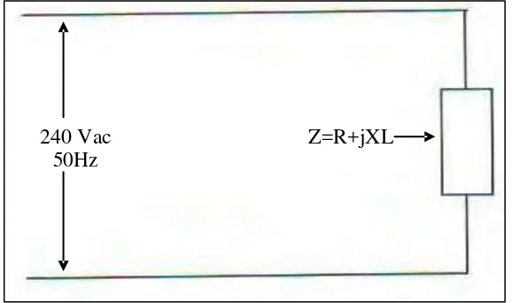
Device that use in residential normally are resistive and inductive load, because that power factor cannot reach 0.9 and reason power efficiency drop. It shows in figure 2.3 and 2.4 shown power triangle uncorrected circuit.
240 Vac Z=R+jXL
[image:24.595.170.459.507.678.2]50Hz