THE DESIGN AND FABRICATION OF HYDRAULIC BOOM TRAINER WITH GRIPPER ATTACHMENT
MUHAMMAD FAIZ BIN OTHMAN
THE DESIGN AND FABRICATION OF HYDRAULIC BOOM TRAINER WITH GRIPPER ATTACHMENT
MUHAMMAD FAIZ BIN OTHMAN
This report is submitted in partial fulfilment of the requirement for the degree of Bachelor of Mechanical Engineering (Thermal-Fluids) with Honours
Faculty of Mechanical Engineering
UNIVERSITI TEKNIKAL MALAYSIA MELAKA
i
SUPERVISOR DECLARATION
“I hereby declare that I have read this thesis and in my opinion this report is sufficient in terms of scope and quality for the award of the degree of Bachelor of
Mechanical Engineering (Thermal-Fluids)”
DECLARATION
“I hereby declared that the work in this report is my own except for summaries quotation which have been duly acknowledged”
Signature : ………..
iii
This report is dedicated to my family. Thank you for your continuous support during my vital educational years. Without their patience, understanding and most of all
love, the completion of this work would not have been possible.
To my beloved mother,
Noraini Binti Suhaimi
My siblings,
ACKNOWLEDGEMENT
“In The Name Of Allah, The Merciful, The Beneficent”
Glory to Allah S.W.T. the most gracious and most merciful. All the worship belongs to only Allah. We seek refuge with Allah from the wickedness within evil and until I have done the project. I also praised to Allah S.W.T for giving us courage, time, and knowledge in completing this report for Bachelor Degree Project.
Alhamdulillah, at last this report is complete to be submitted on the due date. The successful of this project is because of the fully encouragement and support of many people. I wish to express my gratitude to my supervisor, Dr. Ahmad Anas Bin Yusof who was abundantly helpful and offered invaluable assistance, support and guidance and also deepest appreciation to the members of the supervisory committee, Mdm. Fadhilah Binti Shikh Anuar and Mr. Faizil Bin Wasbari. Without their continued support and interest, this thesis would not have been same as presented here.
v
ABSTRACT
ABSTRAK
vii
CHAPTER I INTRODUCTION 1
CHAPTER II
1.1 Background 1.2 Problem Statement 1.3 Project Objective 1.4 Project Scope
LITERATURE REVIEW
2.1 Introduction to Manipulator Arm
2.2 Manipulator Arm for Educational and Research Purpose
CHAPTER III
3.2 Projection and Angle of Motion Review 3.3 Blueprint Design using SolidWorks Software 3.4 Kinematics Analysis
3.4 Component Procurement and Fabrication Process
Attachment 1 : PSM 1 Work Progress Attachment 2 : PSM 2 Work Progress Attachment 3 : Gantt Chart
ix
LIST OF FIGURES
FIGURE TITLE PAGE
1.1 Hydraulic System 2
2.1 Manipulator Arm with (3) three degree of freedom 6
2.2 Manipulator Arm using Syringe 8
2.3 DS4 Training System 9
2.4 Three-link Manipulator Arm 10
2.5 KUKA youBot Manipulator Arm 11
2.6 Robotnik Hydraulic Manipulator Arm 11
2.7 Robotic Arm 2 Basic Kit 12
Hydraulic Manipulator Arm Motion Control
Pneumatics Manipulator Arm using Microcontroller Manipulator Arm with Four Degree of Freedom Denavit-Hartenberg Notation
Flow Chart of Project
Angle Motion of 3 DOF of Manipulator Arm SolidWorks Design of Manipulator Arm
3.4
Cylinder Design Full Assembly Gripper Attachment Parts
Gripper Attachment Full Assembly Arm parts
Manipulator Arm Full Assembly Manipulator Arm Projection View Free Body Diagram for Each Link Free Body Diagram for Link ABC Free Body Diagram for Link CDE Free Body Diagram for Link DEF
Free Body Diagram for Each Link based on Cylinder Displacement
Free Body Diagram for Link ABC
Free Body Diagram for Link DEF and DFG Free Body Diagram for Link HIJ
Free Body Diagram for Gripper Attachment Free Body Diagram for basement rotational Graph of Validation Result for Cylinder 1 Graph of Validation Result for Cylinder 2 Graph of Validation Result for Cylinder 3 Graph of Validation Result for Cylinder 4 Graph of Validation Result for Cylinder 5 SolidWorks simulation in fully retract position SolidWorks simulation in desired position
xi
Work Space area of the end-effector Hydraulic Cylinder
Wood Piece
Bolt, Nut, Washer and Spacer Hydraulic Gripper
Fabricated Gripper Attachment Flow of Fabrication Process Completed Fabrication Process Fitted on portable table
Pneumatic and Hydraulic Circuit
Push Button, DCV, T-connector and tube Flow Control Valve (FCV)
Pressure Regulator Hydraulic Power Unit Pressure Relief Valve Hydraulic Hose Manual Lever DCV Pressure Gauge Hose Connector
Flow Control Valve (FCV) Cylinder Position
Connected Pneumatic Tube Connected Hydraulic Hose
Cylinder Speed Extend Position Data using Pneumatic Extend position for cylinder 1
4.3 4.4 4.5 4.6 4.7
4.8
5.1
Extend position for cylinder 2
Graph of Retract Position using Pneumatic System Retract position for cylinder 1
Retract position for cylinder 2
Graph of Cylinder Speed Extend Position using Hydraulic System
Graph of Cylinder Speed Retract Position using Hydraulic System
Concept of Forward and Inverse Kinematics
47 47 48 48
49
xiii
LIST OF TABLES
TABLE TITLE PAGE
2.1 3.1
4.1 4.2 4.3 4.4
Manipulator Arm Configuration
Degree of Angle from Equation and SolidWorks Simulation
Cylinder Speed Extend Position Data using Pneumatic Cylinder Speed Retract Position Data using Pneumatic Cylinder Speed Extend Data using Hydraulic System Cylinder Speed Retract Data using Hydraulic System
7
CHAPTER I
INTRODUCTION
1.1 BACKGROUND
According to Esposito (2009), fluid power is the technology which involves the use of pressurized gas or fluid in order to generate, transmit and control power. Nowadays, fluid power is one of the major technologies that been applied in almost factory in the world weather in heavy industries or in small industries and also been applied in non-industry sector such as in medical and food processing sector. Besides that, fluid power technology is one of the subject that been though in schools and institutions of higher education. There are a lot of application that used this technology such as fluid power steer and brakes automobiles, offshore, launches spacecraft, drives machine tools and mines coal. The application of fluid power technology is useful in order to perform a certain work that could not be done by human capability. For example lifting heavy load, movement limitation, pull and push heavy load and regulate almost all machines in industries which directly make a work easier and faster. In fact, there is almost all worldwide manufactured that hasn’t been used this technology at specific stage or at certain level in their production or distribution.
2
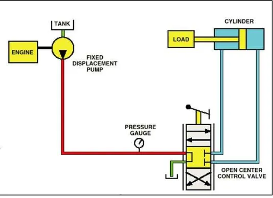
Figure 1.1 Hydraulic System
(Source: http://prayitnoagus.blogspot.com/)
with hydraulic system where actually has two difference types which is fluid transport and fluid power transmit. Fluid power transport is used in delivery a fluid or liquid from one place to another that mostly considers the total amount of transported fluid. Then, fluid power transmit is designed in order to perform a specific work according to require purpose. This type of hydraulic system used a pressurized liquid to transmit power that been generate from hydraulic power unit and been supply to the cylinder for a linear motion and fluid motor for a rotary motion. Figure 1 shows the application of hydraulic system in lifting a load.
1.2 PROBLEM STATEMENT
By referring to Luca & Sicilianot (1993), in reducing costs and improving capability and efficiency of work in the production of a product, the approach of using hydraulic manipulator arm applications is enhanced and expanded. Hydraulic system is one of the subjects in engineering courses in institutions of higher education and the basic of this system also been taught in schools. Hydraulic training kit that commonly used in schools and institutions of higher education only provide the basic equipment, component and tools. Therefore, this hydraulic boom trainer project is proposed in order to provide additional components for hydraulic training kit for future development.
1.3 PROJECT OBJECTIVE
The objective of this project is divided into several specific points:
i. To design and fabricate hydraulic boom or manipulator arm trainer with the concept of gripper attachment with various angle movements which consists of five hydraulic cylinders for the purpose of education and research.
4
1.4 PROJECT SCOPE
The scope of the project is used to show the limitation of the research and give the clearest view of the project. In this project, there is several scope of study involved which is:
i. To design and fabricate a small scale of manipulator arm system for educational purpose or as a training kit.
ii. To develop a manipulator arm system that will be fitted on a portable table and connected with current hydraulic power trainer in Hydraulic and Pneumatic Lab, FKM, UTeM.
CHAPTER II
LITERATURE REVIEW
2.1 INTRODUCTION TO MANIPULATOR ARM
6
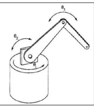
Figure 2.1 Manipulator Arm with (3) three degree of freedom (Source: (Faris et al. 2012))
By referring from previous research Hemami (1988), human arm has (7) seven degree of freedom which capable to do a lot of works with high flexibility of movement while mostly there are only (5) five to (6) six degree of freedom of manipulator arm that already exist in industries. However, human arm has high limitation of doing heavy job and workspace limitation. Therefore, the purpose of developing robotic manipulator arm is to react as a human arm in order to do the works that beyond human capabilities. Robotic manipulator arm has been widely applied in the world industry, such as welding robot, handling robot, punching and cutting robot, machine tools robot and also widely applied for research and educational purpose.
There are various type of manipulator arm which is applied various configuration depending on the level of difficulty of the task or works. This manipulator arm has the advantage of flexibility in the (2) two dimensional work area space so that it is suitable to be applied in most industrial robots. In order to carry out their duties, it needs a planning system movement of the manipulator from the initial conditions to the final conditions in accordance with the tasks that have been given. There are several algorithms that have been raised by some experts to plan the movement of the manipulator to accomplish a task that has been given.
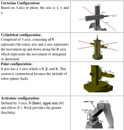
Table 2.1: Manipulator Arm Configuration
(Source: http://didiktristianto.dosen.narotama.ac.id)
same output when working a task repeatedly. So it can be re-programmed functioned for several different tasks and has low percentage of mistakes than humans make, as well as numerous other benefits. However, the movement of the robot control artificial intelligence sometimes still has limitations in some cases such as for more actual movement or more flexible that it is still necessary control is done manually. Due to the variety of shapes and sizes, the manipulator arm also has a variety of movement skills. Physically, there are several configurations can be formed. Most of manipulator arm possess (1) one of the (4) four basic configurations which are polar configuration, cylindrical configuration, Cartesian configuration and Jointed-arm configuration. Table 2.1 shows the figure of manipulator arm configurations.
Cartesian Configuration:
Based on 3-axis or plane, the axis is x, y and z.
Cylindrical configuration:
Comprised of 3-axis, consisting of θ
represents the rotary axis and z axis represents the movement up and down along the R axis which represents the movement of elongated or shortened.
Polar configuration:
It also has a 3-axis which is θ, β, and R. This system is symmetrical because the latitude of robot sphere (ball).
Articulate configuration:
8
Figure 2.2 Manipulator Arm using Syringe
(Source: http://www.cse.iitk.ac.in/users/amit/courses/768/00/atandon/) In the meantime, due to the rapid development of the use of manipulator arm as one approach to make work become easier and faster, the knowledge about the usage and advantages of manipulator arm was introduce starting from earlier education in school. In schools, most of the project on constructing a manipulator arm is using syringe to react as a cylinder and also as a controller to move the manipulator arm. The purpose of this concept is to discuss and analyze the principle of fluid power which is use the under pressure fluids to generate, control, and transmit power. In Sobh et al. (2001) research, most of student in schools were only exposed to the theoretical lesson and spend a lot of time in classroom. Most of the time, they could not adopt and apply practically what they had learn in class in order to analyze result and won’t be able to discuss and doing comparison between theoretical and experimental result. The existing manipulator arm either using pneumatic, hydraulic or servo motor as the main source of power generally is quite expensive and large in size. Besides, the systems of the existing products are more complicated and too sophisticated to be analyzed by student in schools and universities. By developing and constructing the manipulator arm for educational and research purpose which is small in size and with the system that not too complicated, student will be able to understand and learn about the functionality of the system and the main concept of the design. Figure 2.2 shows the example of hydraulic manipulator arm using syringe.
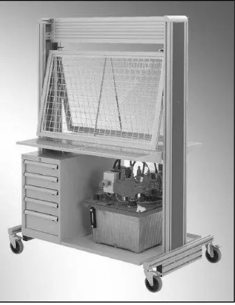
hydraulic training kit in laboratory that been provided for student to learn about the hydraulic system which consists of specific components and tools. The model of this training kit is DS34 Training system which been supplied by Rexroth Bosch Group from Germany. The features of this training kit are to provide training system for basic and advanced due to practical requirement. The main components are consists of stable, steerable castors with integrated hydraulic power unit, an electrical switch box, a tool container, a measuring glass, and a P/T distributor. Therefore, the idea of this project is proposed in order to give other alternative method in learning process and to clearly understanding the application concept that relate to the hydraulic system. Figure 2.3 shows the actual DS4 Training System in FKM Laboratory.
2.2 MANIPULATOR ARM FOR EDUCATIONAL AND RESEARCH PURPOSE
In previous research by Sobh et al. (2001), they had developed concurrent design of a three-link manipulator prototype. They explained the steps on how to produce the proposed prototype in efforts to expand the manufacture on prototyping development for educational and research purpose. Indirectly, they also want to provide a practical approach amount student in order to give the opportunity for them