Bandwidth Widening Strategies for Piezoelectric
Based Energy Harvesting from Ambient Vibration
Sources
Swee-Leong, Kok, Mohd Fauzi Ab Rahman, David Fook Weng, Yap, Yih Hwa, Ho
Faculty of Electronic and Computer Engineering Universiti Teknikal Malaysia Melaka,
Hang Tuah Jaya, 76100 Durian Tunggal, Melaka, Malaysia
Abstract— Due to the fact that the ambient vibration sources are random and unpredictable, therefore a vibration based energy harvesting device is desirable to be able to operate at wider bandwidth in an envelop of frequency range to generate maximum electrical output. In this paper, various ambient vibration from household appliances, machineries, vehicle and moving vehicle were measured and investigated. The second part of the paper will discuss the strategies to harvest these ambient vibration sources. An array of piezoelectric multi-cantilever is proposed to address the issue of single piezoelectric cantilever with high Q-factor. Two configurations of multi-cantilever were fabricated in a form that elevated from the substrate as free-standing structures. One with six cantilevers of constant width but different lengths and another with five cantilevers of constant length but different widths. The measurement and experimental results show a frequency band of 200 Hz to 300 Hz as a common bandwith between the vibration sources and the capability of miniature piezoelectric energy harvester in harvesting maximum electrical energy.
Keywords— Energy Harvesting, Free-Standing Structure, Piezoelectric Micro-Power Generator, Random Vibration Sources, Thick-Film
I. INTRODUCTION
Ambient vibration is ubiquitous, present through the time as long as there is activity related to mechanical oscillation such as those created by machines, household appliances, human walking on flexible platform, earthquake and many more. Due to this fact that it is one of the popular energy harvesting sources for powering electronic devices especially those which are intended to be isolated, embedded in building and in a big number such as wireless sensor nodes.
Ambient vibration sources, however is random and unpredictable which is a critical issue for piezoelectric cantilever based energy harvester with high Q-factor. Resonant devices with high Q-factor has very narrow bandwidth of operation, whereby with a small shift of frequency (±2 Hz) in excitation will lead to a drastic drop in the output power (-3 dB).
One of the ways to increase operating frequency is by utilizing a self-tuning mechanism, where the energy harvester can tune its resonant frequency to match the vibration source on which it is mounted, thereby optimizing its electrical
output. This can be done by altering the parameters of the generator such as the mass, length or the stiffness of the system. Tunable energy harvesters can be classified into two categories; active and passive [1] or intermittent and continuous as described in [2]. Generally, there are two possible methods to increase the operating frequency range; tuning and bandwidth widening [3].
In this paper, bandwidth widening method based on multi-frequency response of cantilever structures was studied. These structures consist of an array of free-standing cantilevers [4] fabricated in a monolithic manner using thick-film technology, which do not require manual assembly of active mechanical structures to the electronic circuits as what the traditional thick-film resonant devices do [5]. The active mechanical structure is a sandwich layer of lead zirconate titanate (PZT) and silver/palladium (Ag/Pd) as the upper and lower electrodes [6]. The active resonant structure is free from clamping to the substrate therefore it is flexible to move in transverse direction at low frequency levels which match to the ambient vibration.
The natural frequency of a cantilever structure can be altered by changing its dimensions and mass according to Bernoulli-Euler equation. When operated in an array of cantilevers with small differences in lengths or masses, they can harvest optimum electrical energy collectively from each of the cantilevers over a wider bandwidth of excitation frequencies as described by Sari et al [3].
Two designs of multi-cantilever systems were fabricated and tested. One of which is a multi-cantilever with six cantilevers (or fingers) of different lengths from 15 – 20 mm. These cantilevers having a uniform width of 5 mm and thickness of 85 µm, produce a range of operational frequency of 240 – 500 Hz. The other design is a multi-cantilever with five fingers of different widths from 2 – 10 mm, having a uniform length of 20 mm and thickness of 85 µm, which has an operation range of 280 – 350 Hz.
II. AMBIENT VIBRATION SOURCES INVESTIGATION
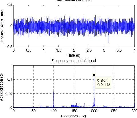
vibration in three different orientations; X, Y and Z. G-Link wireless accelerometer is chosen for the monitoring of ambient vibration source due to the reasons that it is small, portable and can be mounted easily even at a crowded space. To make measurement and monitoring the ambient vibration sources using G-Link, the device has to be mounted firmly on the surface of the vibration sources, ideally either bolted to the surface or mounted with strong magnet. Once the accelerometer node is secured, the G-Link firmware is used to activate the G-Link triggering process. Once the G-link is triggered, it captures the vibration raw data from the vibration sources. This data is then transmitted wirelessly to the base station and finally the data is processed by the host computer. The base station is connected to the host computer via USB connection. The data is then further analysis using a software provided by the manufacturer, where the raw data which is in the time domain is transformed into frequency domain by using FFT, so that, the processed data in the terms of vibration frequency and acceleration level can be clearly presented as shown in Fig. 2.
Fig. 1: G-Link 3-D wireless accelerometer node and the designated channel of 1, 2 and 3 denoted in the text as X, Y and Z respectively.
Fig. 2: Vibration measurement data from a microwave in time domain and frequency domain.
G-Link node has three channels; 1, 2 and 3. Each of the channels represents the orientation of X, Y and Z directions. Fig. 3 illustrates the position of the G-Link node being mounted on the tested ambient vibration surface which is in
this case is a microwave oven, a vehicle and an air handling unit.
Fig. 3: G-Link accelerometer mounted on (a) Microwave casing, (b) bonnet of a car and (c) air handling unit.
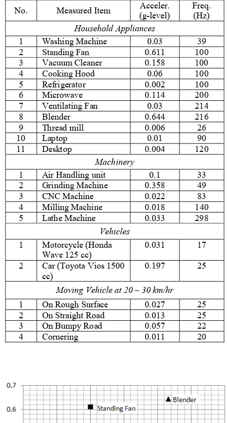
The ambient vibration sources are classified into a few categories; household appliances, machineries, vehicles and moving vehicles. The result of the measurements is summarized in Table 1. Fig. 4 shows the plot of acceleration level against the frequency of the vibration sources.
The level of vibration in term of acceleration (g-level) and the frequency of the vibration sources are two important parameters in designing micro-power generator in order to harvest maximum electrical power. The relation between the harvested power, P and the ratio of the external excited vibration frequency,ω and the system natural frequency, ωn is given by [7],
(1)
where M is the lump mass, ζT is the total damping ratio, ζe is the electrical damping ratio and Y is the amplitude of vibration.
Equation (1) can be simplified into equation (2) when the device is operated at its resonant frequency ωn.
(2)
The Maximum power increases exponentially with the incremental of acceleration level, ain. An acceleration level of bigger than 50 mg is considered as useful vibration sources for
0 0.5 1 1.5 2 2.5 3 3.5 4
-0.5 0 0.5
Time domain of signal
Time (s)
Inphas
e A
m
pl
it
ude
0 50 100 150 200 250 300
0 0.05
0.1 X: 200.1
Y: 0.1142 Frequency content of signal
Frequency (Hz)
A
c
c
e
le
ra
ti
o
n
(g
)
2 2 2
2 3 3
1 2
⎥ ⎥ ⎦ ⎤ ⎢
⎢ ⎣ ⎡
⎟⎟⎠ ⎞ ⎜⎜⎝ ⎛ − + ⎥ ⎦ ⎤ ⎢
⎣ ⎡
⎟⎟⎠ ⎞ ⎜⎜⎝ ⎛
⎟⎟⎠ ⎞ ⎜⎜⎝ ⎛
=
n n
T
n
e Y
M P
ω ω ω
ω ζ
ω ω ω ζ
(
)
22
max
4 n e m
in ea M P
ζ
ζ
ω
ζ
+ =
X Y
Z
Y
X Z
Y
X
Z
(a) (b)
powering low power electronic devices as reported by Torah et al [8].
Table 1: Summary of measured vibration sources
No. Measured Item Acceler. (g-level)
Freq. (Hz)
Household Appliances
1 Washing Machine 0.03 39
2 Standing Fan 0.611 100
3 Vacuum Cleaner 0.158 100
4 Cooking Hood 0.06 100
5 Refrigerator 0.002 100
6 Microwave 0.114 200
7 Ventilating Fan 0.03 214
8 Blender 0.644 216
9 Thread mill 0.006 26
10 Laptop 0.01 90
11 Desktop 0.004 120
Machinery
1 Air Handling unit 0.1 33 2 Grinding Machine 0.358 49
3 CNC Machine 0.022 83
4 Milling Machine 0.018 140
5 Lathe Machine 0.033 298
Vehicles
1 Motorcycle (Honda Wave 125 cc)
0.031 17
2 Car (Toyota Vios 1500 cc)
0.197 25
Moving Vehicle at 20 – 30 km/hr
1 On Rough Surface 0.027 25 2 On Straight Road 0.013 25 3 On Bumpy Road 0.057 22
4 Cornering 0.011 20
Fig. 4: Plot of acceleration level Vs frequency of various ambient vibration sources potentially to be used for energy harvesting.
It can be noticed from the summarized figure in Fig. 4 that there are a few vibration source with level large than 50 mg. Vibration from a blender, standing fan and grinding machine are the prominent sources for energy harvesting.
Since a device with low natural frequency is usually big in size and often external mass is needed to attach at the end of the cantilever, which is not desirable for miniature devices, therefore vibration sources with higher frequency, > 100 Hz is chosen. In this case, standing fan, blender, microwave and ventilating fan and lathe machine are good candidates.
III.PIEZOELECTRIC CANTILEVER MODEL
Generally, the base excited harmonic motion is modelled as a spring-mass-damper system with the equation motion,
(
−
)
+
(
−
)
=
0
+
b
x
y
k
x
y
x
M
(3)where y denotes the displacement of the base and x the displacement of the mass from its static equilibrium position. The vibration body is assumed to have a harmonic motion,
( )
t
Y
t
y
=
sin
ω
(4)From the Bernoulli-Euler equation derivation, a thin cantilever beam with one end clamped and the other end free, the natural transverse vibration can be written as,
ρ
π
T
b T i i
e
l
h
v
f
⎟⎟⎠
⎞
⎜⎜⎝
⎛
=
22
2
2
(5)
where
v
i is a coefficient related to boundary conditions, hT is the total thickness of the cantilever beam, lb is the length of the cantilever beam, eT is the resultant elastic modulus and ρ is the density of the structure.Fig. 5: A schematic diagram of a sandwiched piezoelectric cantilever
the amount of voltage generated can be simplified in complex equation as,
(6)
where
e
Tis the resultant elastic modulus, hPZT is the thickness of the piezoelectric materials, β is the distance from the centroid of the layer of PZT to the neutral axis of the structure,ain is the excitation acceleration, lb is the length of the beam, ζT is total damping ratio of the cantilever structure, R is the resistive load and Cp is the capacitance of the piezoelectric materials. d31 and εare the piezoelectric charge and dielectric constant of the piezoelectric material respectively.
Although the model is somewhat oversimplified, it does give a reasonable good approximation for the voltage generated and will be used to compare with the experimental results in this work.
IV.MULTI-FREQUENCY THICK-FILM CANTILEVERS
Two configurations of cantilever arrays were designed and fabricated as shown in Fig. 6. One of which is an array of cantilever with six fingers having different lengths and the other is having five fingers having different widths. The dimensions of the devices are designed according to the limitation of screen-printing process and thick-film processing technique.
Fig. 6: An array of cantilever with (a) six fingers having different length and (b) an array of cantilever with five fingers having different width
Both of the configurations having same thickness of 50 µm and an elevated gap height from the substrate of 1.2 mm. Configuration 1 having standard width of 5 mm with varying lengths of 15 – 20 mm. Configuration 2 having standard length of 20 mm with varying widths of 2 – 10 mm.
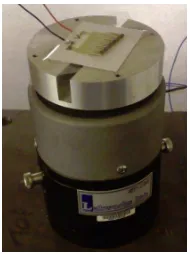
The devices were tested on a vibrometer as shown in Fig. 7, at a harmonic excitation over a range of different frequencies close to the resonant frequency of the cantilevers at a constant acceleration level. The acceleration level is a function of the frequency according to 2
ω
Yain= . To maintain the acceleration level, therefore needs a feedback system. An accelerometer in the vibrometer measures the actual value of the frequency and acceleration level and is feedback into a
comparator to compare with the set point. A processed signal is then generated and amplified to drive the vibrometer to produce the desired acceleration level at a given frequency.
Fig. 7 Device under test on a vibration generator
V.RESULTS AND DISCUSSION
Fig. 8 shows the experimental results of the cantilever array of configuration 1 at an excitation frequency of 220 Hz to 520 Hz at a constant acceleration level of 0.5 g. The output voltages were measured when driving a resistive load of 25 kΩ. The performance of the cantilever array was compared to a reduced number of cantilever by breaking off one by one began with the longer to shorter cantilever of the array. It is noticed that, the peak of the output voltage increases as the number of the cantilever decreases. This is due to the loading effect of the piezoelectric material of the cantilever array, which appears to be electrically connected in parallel. It is also noticed that the maximum voltage generated occurs at the resonant frequency of each individual cantilever with different lengths, which is in a good agreement with the equation (5).
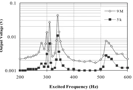
In another experiment, the cantilever array of configuration 2 (having different widths) was excited to a range of frequency between 200 Hz to 600 Hz and the performance of the energy harvester is shown in Fig. 9. It is noticed that the pattern of the frequency peak is irregular and concentrated at around 350 Hz, which is coincident to the resonant frequency of finger 3 of configuration 1, having a standard length of 20 mm and width of 5 mm. It is also noticed that, there is another resonant peak at around 520 Hz in the frequency excitation range. Therefore, it can be concluded that the width of the cantilever is influencing the performance of the cantilever array at some extend but not widening the operating frequency of the energy harvester. In the order hand, the narrower the cantilever the more susceptible it would be to excite to higher order vibration mode. This has to be taken into account when fabricating energy harvesting devices using brittle and fragile ceramic piezoelectric materials.
The voltage output of the individual cantilever is dependent on the inherent and the structure of the piezoelectric cantilever, as shown in equation (6). One of the easiest controllable parameters is by changing the length of the cantilever suit to the excitation frequency to achieve high
(a) (b)
⎪⎭ ⎪ ⎬ ⎫ ⎪⎩
⎪ ⎨ ⎧
⎥ ⎥ ⎦ ⎤ ⎢
⎢ ⎣
⎡ +
− =
p r T r r T b
in PZT T
RC k j l
a h d je V
ω ζ ω ω ζ ε
β
2 4
3
2 31 2 2 2
voltage output. As electrical power is the major concern for most low power electronic devices, therefore it has to be examined closely. The electrical power output from the piezoelectric devices is Pmax = V
2
/R, where the R is the resistive load. The power output can be further increased by increasing the excitation g-level as according to equation (2).
VI.CONCLUSION
The purpose of this paper is to investigate the ambient vibration sources and to demonstrate the possibility of widening the bandwidth of thick-film piezoelectric cantilever in harvesting energy from the ambient vibration sources. Although the experimental results show maximum voltage output generated by piezoelectric energy harvesters are in the frequency range of 200 Hz to 500 Hz, which is not exactly matched to the ambient vibration sources of 50 Hz to 300 Hz, but it shows an overlapping frequency range of 200 Hz to 300 Hz, which is a frequency band that can be explored further for fabricating miniature energy harvesters without the necessary of attaching proof mass at the end of the cantilever.
REFERENCES
[1] S. Roundy, E. S. Leland, J. Baker, E. Carleton, E. Reilly, E. Lai, B. Otis, J. Rabaey, P.K. Wright, and V. Sundararajan, “Improving power output for vibration-based energy scavengers”. IEEE Pervasive Computing, 2005. 4: p. 28-36.
[2] D. Zhu, M. J. Tudor, and S.P. Beeby, “Strategies for increasing the operating frequency range of vibration energy harvesters: a review”.
Meas.Sci.Technol., 2010. 21(2).
[3] I. Sari, T. Balkan, and H. Kulah, “An electromagnetic micro power generator for wideband environmental vibrations”. Sensors and Actuators A: Physical, 2008. 145-146: p. 405-413.
[4] S. L. Kok, N. W. White, and N. R. Harris, “Free-standing thick-film piezoelectric device”. Electronics Letters, 44 (4). 2008 pp. 280-281. ISSN 0013-5194
[5] N. M. White, P. Glynne-Jonnes, S. P. Beeby, “A novel thick-film piezoelectric micro-generator”, J. Smart Mater. Struct., vol. 10, p. 850 – 852, 2001.
[6] S. L. Kok, N. M. White, N. R. Harris, “Fabrication and characterization of free-standing thick-film piezoelectric cantilevers for energy harvesting”, Measurement Science and Technology, 20 (124010), 2009. [7] C. B. Williams, and R. B. Yates, “Analysis of a micro-electric generator for Microsystems,” Transducers 95/Eurosensors IX, 1995: p. 369-372.
[8] R. Torah, P. Glynne-Jones, M. Tudor, T. O’Donnell, S. Roy and S. Beeby., "Self-powered autonomous wireless sensor node using vibration energy harvesting," Measurement Science and Technology,2008 vol. 19, p. 125202.
[9] S. Roundy, and P. K. Wright, A piezoelectric vibration based generator for wireless electronics. Smart Materials and Structures, IOP, 2004. 12, p 1131-1142.
ACKNOWLEDGMENT
The authors would like to acknowledge the support of this work by Universiti Teknikal Malaysia Melaka (UTeM) on short term research grant no. PJP/2011/FKEKK(21C)S00901
Fig. 8: Experimental results of the output voltage (at a resistive load of 20 kΩ) at an excitation frequency in the range of 220 to 520 Hz with an acceleration
level of 5 g, for the cantilever array of configuration 1.
Fig. 9: Experimental results of the output voltage at an excitation in the range of 200 – 600 Hz with an acceleration of 5 g for the cantilever array of
configuration 2 at the resistive load of 5 kΩ and 9 MΩ. .
0 0.02 0.04 0.06 0.08 0.1
220 270 320 370 420 470 520
O
p
en
C
ir
cu
it
V
o
lt
a
g
e
(V
)
Excited Frequency (Hz)
6 Fingers 5 Fingers 4 Fingers 3 Fingers 2 Fingers 1 Finger
O
u
tp
u
t V
ol
tage
(V
)
0.001 0.01 0.1
200 300 400 500 600
O
u
tp
u
t V
o
lt
a
g
e
(V
)
Excited Frequency (Hz)
9 M 5 k
O
u
tp
u
t V
ol
tage
(V