I hereby declare that I have read this project report and found its content and from to meet acceptable presentation standards of scholarly work for the award of Bachelor of Mechanical
Engineering (Structure and materials)
ii
DECLARATION
I declare that this project report entitled “To design and fabricate projectile motion
prototype device for students use in dynamic laboratory” is the result of my own
research except as cited in the references.
iii
iv
ACKNOWLEDGEMENT
First of all, my heartiest appreciation to my final year project supervisor, Mr. Nor Azmmi Bin Masripan for his guidance, advice, support which have put me in a well study curved line which directly contributed thoroughly to the success of this project. His idea, experience and knowledge had been aspiring to me abundantly.
v
ABSTRACT
vi ABSTRAK
vii
TABLE OF CONTENT
CHAPTER TITLE PAGE
DECLARATION ii
DEDICATION iii
ACKNOWLEDGEMENT iv
ABSTRACT v
ABSTRAK vi
TABLE OF CONTENT vii
LIST OF TABLE xi
LIST OF FIGURE xii
LIST OF SYMBOL xvi
I INTRODUCTION
1.1 Objective 2
1.2 Scopes 2
1.3 Problem Statement 2
1.4 Flow Chart for PSM 1 3
viii
II LITERATURE REVIEW
2.1 History of Projectile Motion 6
2.2 Projectile Motion 7
2.3 Reasoning about Projectile Motion 10 2.4 Cranz’s ‘‘Normal Trajectories’’ 11 2.5 Projectile Motion Situation 12
2.6 Springs 18
2.7 Mechanical spring cylinders a design profile 21
III METHODOLOGY
3.1 Introduction 24
3.2 Methodology Flow-Chart 25
ix
3.8 Computer-Aided Design (CAD) 33
3.9 Solid Works Application 34
3.10 Prototype design 35
IV RESULTS
4.1 The Working Procedure of Making the
Model of Projectile Motion device 36
4.2 Equipment and Apparatus 42
4.4 Sample Calculation for Maximum Height 50 4.5 Sample Calculation for Maximum Range 51
x
4.7 Experimental Result 53
4.8 Sample Calculation of Stiffness, k 56 4.9 Sample Calculation of force 57
4.10 working Concept 58
V DISCUSSION
5.1 Graph 60
5.2 Data 61
5.3 Design 62
VI CONCLUSION AND RECOMMENDATION
6.1 Conclusion 63
6.2 Recommendation 64
REFERENCE 65
BIBLIOGRAPHY 66
xi
LIST OF TABLE
No. TITLE PAGE
4.2 Table of two Variable Angle and Velocity 52
4.3 Table of two variable Angle and Velocity (experimental) 52
4.4 Table Angle of inclination (result) 53
xii
LIST OF FIGURE
No. TITLE PAGE
1.1 Stage of PSM1 1
1.2 Stage of PSM 2 4
2.1 Galileo application on cannon 6
(Source: Joseph W. Dauben, 1991)
2.2 The parabolic trajectory of a bouncing ball 7 (Source: Raymond A. Serway.2001)
2.3 A projectile launched with initial velocity. 8 (Source: Raymond A. Serway.2001)
2.4 The velocity and acceleration vectors of a 9 projectile moving along a parabolic trajectory
(Source: Randall D.Knight.2008)
2.5 A projectile launched horizontally falls in 10 the same time as a projectile that is release from rest.
xiii
2.6 A projectile follows a parabolic trajectory because it 11 “falls” a distancebelow a straight-line trajectory.
(Source: Randall D.Knight.2008)
2.7 Non-rigidity of the Trajectory by Cranz’s 12 ‘‘Normal Trajectories’’
(Source: Michael A. B. Deakin.1997)
2.8 The position vector r of a projectile whose initial 13 velocity at the origin is.
(Source: Randall D.Knight.2008)
2.9 A projectile fired from the origin with an 17 initial speed of 50 m/s at various angles of projection.
xiv
3.3 The design of projectile motion prototype equipment 35
xv
4.13 Step 2 of bending process 43
4.14 Chop saw with fiber disc 44
4.15 Shearing machine 45
4.16 Table drill 46
4.17 Metal inert gas (MIG) set. 47
4.18 Hand Grinder 48
4.19 Digital Camera 49
4.20 Graph of Angle versus Velocity 54
4.21 Graph of Angle versus Time 54
4.22 Graph of Angle versus Horizontal Distance 55
4.23 Graph of Angle versus Maximum height 55
xvi
LIST OF SYMBOL
= Initial velocity ( ) = angle (rad)
= Acceleration,( )
= distance,
= Gravity
= Time, )
= height ( )
= Force ( )
= Stiffness
= Length
u = Work done(N)
o
= Degree
1
CHAPTER I
INTRODUCTION
Generally, the high school and university students meet many difficulties in understanding of plane motions, although these are daily observed. Such difficulties are relative either to vectorial characteristic of involved kinematic quantities and to various ways in which the same quantities can be graphically represented.
Other difficulties are relative to abstraction with which normally the concept of function is usually introduced without any connection to concrete experiences. It is necessary to underline that, although velocity and acceleration are terms of common language, frequently the students do not distinguish this quantities between them, with important consequences in correct understanding of Dynamics.
Furthermore, the overall of the design is very user friendly compare to the old design. The main purpose of this section is to find the user of this projectile launcher, to research and planning. By doing so, the user especially student will be determined, the situation need to be analyzed the student specification can be generated and proper planning can be constructed. This step is important to ensure that are design in not an obsolete design and it will fulfill the student needs.
2
design involved, not neglecting the recreational aspect, useful for making the use of this machine either attractive or thought-provoking.
1.1 Objective:
a) To design and fabrication machine heave for students' use in dynamic laboratory for experiment projectile motion.
b) Propose a new design for the projectile motion.
c) To get the comparison between the theoretical value and experimental value.
1.2 Scopes
a) Literature review on projectile motion.
b) Design a projectile motion launcher by using Solidwork(3D). c) Fabricate a prototype of projectile motion launcher.
d) Testing the design that had been fabricated.
1.3 Problem Statement
3
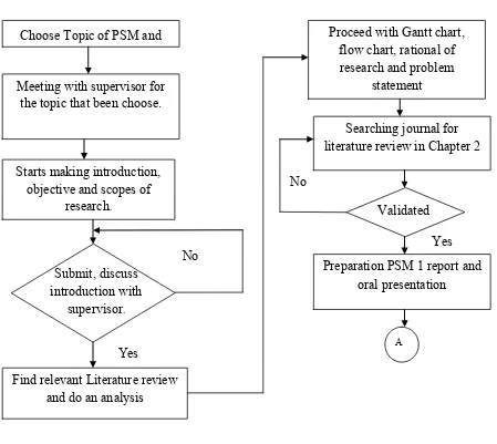
1.4 Flow Chart for PSM 1
Figure 1.1: Stage of PSM1 Choose Topic of PSM and
supervisor
Meeting with supervisor for the topic that been choose.
Starts making introduction, literature review in Chapter 2
Find relevant Literature review and do an analysis
Validated No
Yes Preparation PSM 1 report and
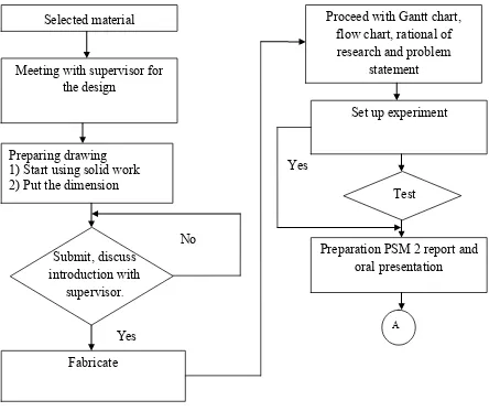
4 1) Start using solid work 2) Put the dimension
5
1.6 Research Frame
6
CHAPTER II
LITERATURE REVIEW
2.1 History of Projectile Motion
In the early of discovery of projectile motion, motion of projectile of shot object (i.e a cannon ball) is thought a straight line until it lost its impetus, at which point it fell abruptly to the ground a show in figure 2.1. This theory was based on Aristotle’s views of motion. However, Galileo realized that projectiles actually follow a curved path, as this is following illustration shows and he is the first person who ever accurately described projectile motion.
7
Galileo said that projectile motion could be understood by analyzing the horizontal and vertical component separately, he even took this idea further with his realization there was more than one force in projectile motion. By utilizing these revolutionary insights, he then concluded that the curve of projectile is a parabola. This idea have help us examine how two objects which in vacuum can hit the ground at the same time even with different shape and mass if both are dropped from the same height.
2.2 Projectile Motion
Baseballs and tennis balls flying through the air, Olympic divers, and daredevils shot from cannons all exhibit is a projectile motion. A projectile is an object that moves in two dimensions under the influence of only gravity. Projectile motion is an extension of the free-fall motion, detail this is to neglect the influence of air resistance, leading to results that are a good approximation of reality for relatively heavy objects moving relatively slowly over relatively short distances. Projectiles in two dimensions follow a parabolic trajectory like the one seen in figure 2.2.