MobiLe robot in inteLLigent SpAce
hairol nizam Mohd. Shah1, Marizan Sulaiman2, and Syed najib Syed Salim3
1, 2, 3 Faculty of Electrical Engineering
Universiti Teknikal Malaysia Melaka, Karung Berkunci 1200, Ayer Keroh, 75450 Melaka E-mail: [email protected]
abstract
This paper introduces the fuzzy logic approach for mobile robot in intelligent space. There are three major algorithms involved. They are object classiication, object tracking and obstacle avoidance. The inputs are received from cameras which are mounted on a ceiling. The main idea of the object classiication is to classify objects into three categories depending upon their colors; the categories are mobile robot, destination and obstacle position. These categories are represented by X symbol with different colors. This system is to “teach” and “train” the mobile robot proceeding to destination without hitting the obstacle. The mobile robot is autonomous; that means, it could be pursuing to the target position automatically without user guidance. In this project, fuzzy logic is used to guide the mobile robot direction until it reaches the target position. This system is generated in real-time and suitable for indoor environment applications. One of the advantages of this project is that it only uses, a camera and image processing generated by the algorithms itself without additional sensor such as sonar or IR sensor.
Keywords: Intelligent Space, Objects Classiication, Object Tracking, Obstacle Avoidance and Fuzzy Logic
1.0 introduction
This project introduces how to “train” an autonomous mobile robot going to the target destination without being user guided. The input image is captured using a single camera to store the image processing load. The different threshold value based on the hue saturated color value will be applied. The idea to use the two time threshold which is in saturation area and in hue saturated area. The set-up consists a mobile robot, destination and obstacles whose locations are determined using center of area as a reference. For estimating the actual object location,
camera is ixed to a ceiling and the camera needs to be set. The
camera setting includes the length between the camera to area envelope and the camera focus.
This research provides some facilities for acquiring images directly from a camera. This capability can skip the steps
involved in using two separate programs which is irst to control
the acquisition and second for data analysis. As an initial step during the implementation process, there are several algorithms involved for driving the mobile robot. The algorithms are
object classiication, object tracking and obstacle avoidance
algorithms. The details about the algorithms will be discussed later.
After almost 40 years of research, computer vision is still an open area. Clearly then, the complete solution to this problem in a general environment is still a long way off, and so the particular solution derived from this work will be for a very constrained environment. Nonetheless, it will be another step towards the ultimate goal of comprehensive robot vision of the
kind that presently exists only in the realm of science iction
2.0 LiterAture review
Robots in science iction have exhibited considerable visual
acuity and high-level reasoning. For instance, the android played by Robin Williams in the movie The Bi-Centennial Man was capable of human-like behavior and developed skills in
sculpting and woodwork that require extremely good vision as
well as perceptual understanding. The current state of the art is
far less impressive than these ictional robots.
Intelligent Space (iSpace) has been active since 1996 and
expending with more and more functions. The concept of iSpace is not limited to a local space [1] but can be extended to a virtual space around the word and beyond. For example when we say
“tea”, the voice recognition in iSpace will send a command to the center controller where it computes and processes any necessary procedures to send a mobile robot to bring a cup
of tea. Another iSpace concept is related also for example an
intelligent environment was proposed a few years ago to be used in the control automation area, for intelligent navigation
and intelligent manufacturing to enhance eficiency.
There are many different methods employed in mobile robotics for navigation. Some researchers have their own techniques to construct the navigation system. The navigation system includes how to ovoid the obstacle, classify and tracking
the objects. To implement objects classiication algorithms
many researchers they are base on color histogram [2], motion detection [3] and template matching [4]. Color histogram is based on grey histogram value level means every color has their
own grey value so that the classiication process is according
to that value. The most straightforward approach to motion
detection is image subtraction. For example each frame C in
the sequence was subtracted from the reference frame R such as an image of the empty court, yielding the difference image D where R, G and B denote the red, green and blue components of the current frame and the reference frame as:
D = RR – RC + GR – GC + BR – BC (1)
In template matching process a “templates” have be deined irst in 2D functions which extract the very basic appearance
of the objects. The “templates” take over the weakness of
Journal - The Institution of Engineers, Malaysia (Vol. 68, No.4, December 2007)
Journal - The Institution of Engineers, Malaysia (Vol. 69, No.4, December 2008)
feature set when a shape of objects varies over time and image resolution is low. Majority of researchers [2,5] use color to classify the objects because it is more practical to compare motion or template matching. The reason is there no need for other information like sensors or to train the “templates” for matching process.
Normally to avoid an obstacle the mobile robot or robot need “additional outside information” such as sensors [5, 6, 7]. Some researchers apply genetic algorithms (GA) [8] and chain rule [6] to avoid the obstacle. The GA is based on the mechanics of natural selection and genetic process of biological organisms.
The result of GA is search algorithm with innovative lair of
human search. The chain codes are used to represent a boundary
by connected sequence of straight-line segments of speciied
length and direction. Typically, the chain codes representation is based on 4 or 8 connectivity of the segments. The direction of each segment is coded by using a numbering such as shown in Figure 1. Chain rule is base on two different ways of computing perimeters. The value of perimeters is the actual boundary
pixels of the object. The value of outside perimeter is actually required of the mobile robot to move to boundary pixels that
have been traverse before.
Figure 1 : chain code directions
Fuzzy logic is a medium for making decision for the robot
where the robot should going next. The inputs are usually taken
by additional outside information such as sensors [9, 10]. Fuzzy logic rule normally can be constructed either 5 inputs and 25 outputs or 3 inputs and 9 outputs depend on theirs inputs. In previous researcher many of them applied 5 input and 25 output [5, 11]. In this research, the fuzzy logic inputs are not from
sensors but come from classiication and tracking algorithms
process in terms of angles which are back-front and in-front mobile robot angles.
Majority of research concentrate on the intelligence part, that means what robots can do. The intelligence part [12] included in manufacturing plants, an automatic fork lift can be moved around to convey parts from one point to another point is included in the host computer, mobile robot, communication module and vision system. In hospitals, a service robot can help to bring food and medicine to patients; or even at homes, we
can have a robot to serve a cup of coffee, clean the loor, or
even take care of the grass in our garden.
3.0 inteLLigent SpAce robot SySteM
Intelligent Space (iSpace) is a space such as a room, corridor or street which has distributed sensor, controllers, and actuators that are capable of providing intelligent services. In order to
make industrial processes highly eficient, iSpace fuses global
information within the space of interest to effectively and
eficiently make intelligent space operation decisions such as
how to move a mobile robot from one location to the other. In iSpace, the mobile robot required to move one location to the other without colliding with the obstacle.
In the iSpace system, the autonomous mobile robot pursues to the targeted destinations without user guidance. The system in this project operates based on color image from a two static camera which installed on the top of workspace (iSpace) area. Currently the mobile robot only moves within the workspace area as determined by fuzzy logic rules. In the previous research [9,10] of iSpace the mobile robot system mostly used sensors to avoid the obstacle, the scheme which works reliably in indoor and outdoor environments. The different approach in the present work is to replace the sensor; instead the use of the camera and the mobile robot system is fully generated by algorithms inside the systems.
The system that is designed for the iSpace application can control the mobile robot from a control unit room. The user can monitor the mobile robot activities such as position or location without going to the real workspace area. The iSpace system
involves software for image acquisition, object classiication,
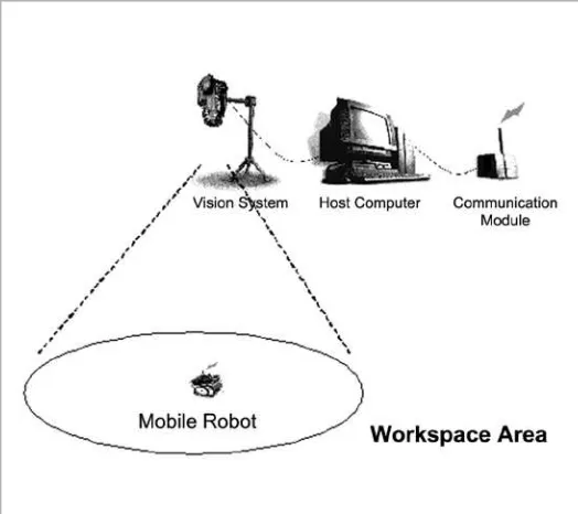
object tracking and obstacle avoidance. It also needs various additional hardware which includes mobile robot platform and communication device between mobile robot platform and host computer. Figure 2 shows the organisation for an intelligent mobile robot in the iSpace system. The intelligence part [12],
for example, in manufacturing plants, an automatic fork lift can
be moved around to convey parts from one point to another point is included in the host computer, mobile robot, communication module and vision system.
Figure 2 : Organisation of intelligent mobile robot in intelligent space (ispace) system
3.0 ALgorithMS deveLopMent
The overview of our real time object classiication, object
Figure 3 : the system block diagram
3.1 object cLASSiFicAtion ALgorithM
The main idea in classiication algorithm is to classify the objects into the suficient number of classes [3, 13] It is veryimportant to recognise the type of a detected object in order to track it reliably in order to analyse its activities correctly. The initial color models of the new objects are also obtained in the
object classiication. This color based on the gray histograms
value of the objects. The gray histograms of the objects are used
for the appearance based identiication of the gray value.
The local color models are produced from the saturated hue
values which have been collected after the object classiication
process started. Saturated hue value has been compensated the weakness [2] of saturation value to determine the colors in the image sequence. This is because by using saturation value, the different colors with the same range of the saturation are
dificult to determine. Depending on this situation, we need
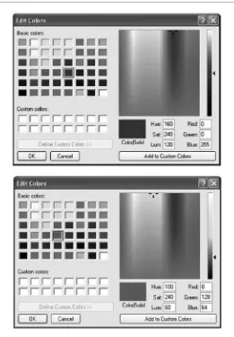
two components to determine the colors. Figure 4 shows the illustration of saturation and hue value. In the illustration, the saturation for both the blue and green colors is the same is around 240 but the hue and luminosity are different.
3.2 object trAcKing ALgorithMS
The tracking process works for tracking of the object region
recognised in the object classiication process. Tracking process
receives the local color models, initial location and area of
objects from the object classiication process. Local color
models are for objects tracking and objects segmentation under the occlusion in one camera image [2].
The aim of object tracking is to establish a correspondence between objects or object parts [14] in consecutive frames
and to extract the temporal information about objects such as
trajectory, posture, speed and direction. In this case, the focus is on the direction and position of the objects. Tracking algorithm is to detect objects frame by frame and compares the objects image position [13] between them based on local color models. In this algorithm the mobile robot, destinations and obstacle will be tracked.
3.3 obStAcLe AvoidAnce ALgorithMS
The aim of the obstacle avoidance [7] is to give information
to the mobile robot either in-front of it there exists an obstacle or
not. Region of interest (ROI) is used as a guidance to determine the obstacle. The object which is detected by the camera inside their boundary is considered as the mobile obstacle. The way to avoid the obstacle is to adopt the fuzzy logic rule to design the environment recognition and collision avoidance for the mobile robot. Figure 5 shows how to determine the obstacle.
A simple approach to obstacle avoidance was taken, based on the regions boundary (ROI) that when the mobile robot will completely inside that region. Some assumptions was make in the region of interest (ROI) in order to make avoidance is
completely done by setting the actual boundary 4 pixels larger
from the real size. The description of obstacle avoidance points is shown in the Figures 6 (a) and (b). The mobile robot will turn around and move around the obstacle [15] in the other direction towards to the avoidance points. Clearly, the avoidance points
Figure 4 : the illustration of saturation and hue value
will be determined by the obstacle regions boundary. For example
if the mobile robot is moving to the destination from left to right as shown in Figure 6 (a) currently the mobile robot position in region II, the avoidance points to colliding the obstacle is A. The mobile robot should be move to the point A guided by fuzzy logic rule. Figure 6 (b) shows if the mobile robot is moving to the destination from right to left.
Figure 6 (a) : the description of obstacle avoidance from left Figure 6 (b) : the description of obstacle avoidance from right
4.0 Fuzzy Logic ApproAch
Fuzzy sets and systems constitute one of the most fundamental
and inluential computational intelligence tools [9]. The success of Fuzzy Logic Control (FLC) is owed in a large part to the
technological [16] ability to convert qualitative linguistic
description into complex mathematical functions and the ability
to ideal with various situations without analytical model of the environment.
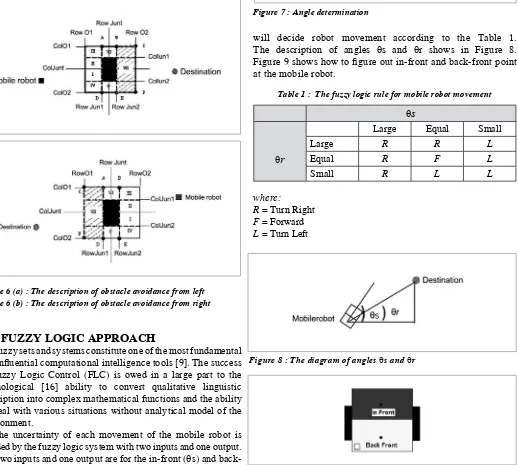
The uncertainty of each movement of the mobile robot is decided by the fuzzy logic system with two inputs and one output. The two inputs and one output are for the in-front (θs) and back-front (θr) angles and the output is the mobile robot movement decision. The output of the mobile robot represented into three
types. The types are turn right (R), turn left (L) and forward (F).
The angle (θ) can be obtained from a function arctan2 [17] as given in Equation (2), between the mobile robot and destination coordinates in terms of column(Y) and row (X). Figure 7 shows the diagram of how to determine the angle (θ). The presented fuzzy logic system uses nine rules as listed in Table 1.
θ = arctan2 (Y, X) (2)
Both of the angles θs and θr should be compared with θref (initial back-front mobile robot angle) to get the condition of angles θs and θr which is large, equal or small. This condition
will decide robot movement according to the Table 1. The description of angles θs and θr shows in Figure 8.
Figure 9 shows how to igure out in-front and back-front point
at the mobile robot.
θ
s
θ
r
Large Equal Small
Large R R L
Equal R F L
Small R L L
where: R = Turn Right
F = Forward
L = Turn Left
The fuzzy logic system is a medium to make a decision [18, 19] where the mobile robot should be going to. A controller is needed with the main function is to move the mobile robot to the desired positions or destinations. The PID controller is the easiest way to embody among many controlling ways [14]. The function position controls the angle and position of a robot at the same time. To move the robot to a desired position, it can be rotated to an angle and go straight ahead. The destination position (d_e) and destination angle (θ_e) formulas are shown in Equations (3) and (4) [5, 20]. The details parameter of the robot description in space is shown in Figure 10.
Figure 7 : angle determination
table 1 : the fuzzy logic rule for mobile robot movement
Figure 8 : the diagram of angles θs and θr
d_e = dx2 + dy2 (3)
θ_e = θ_d – θ_r (4)
The mobile robot rotates only at angular speed in the condition that there is no linear speed. To rotate the mobile robot, the
direction between right motor (VR) and left motor (VL) should
be in the opposite directing, so according to Equations (5) and (6) [21], the calculations are the same as follows, depending on the distance gained (Kd) and angle gained (Ka):
VL = Kd*d_e - (Ka* θ_e) (5)
VR = Kd*d_e + (Ka* θ_e) (6)
The distance gained (Kd) and angle gained (Ka) is set around 0 to 1.0. If the gained were set close to 1.0 the speed of motor rotation going fast otherwise going slow when the gained were set close to 0. No matter what the rotation of right motor (VR)
and the rotation of left motor (VL) would be, the movement of
mobile robot should be follow the rules as:
Rule 1; IF θs is Large and θr is Large, Then direction is R (7)
Rule 2; IF θs is Large and θr is Equal, Then direction is R (8)
Rule 3; IF θs is Large and θr is Small, Then direction is R (9)
Rule 4; IF θs is Equal and θr is Large, Then direction is R (10)
Rule 5; IF θs is Equal and θr is Equal, Then direction is F (11)
Rule 6; IF θs is Equal and θr is Small, Then direction is R (12)
Rule 7; IF θs is Small and θr is Large, Then direction is L (13)
Rule 8; IF θs is Small and θr is Equal, Then direction is L (14)
Rule 9; IF θs is Small and θr is Small, Then direction is L (15)
The rule is only as a guide to decide the right direction of mobile robot going to but the speed of mobile robot is depends
on the value of VR and VL.
5.0 reSuLt oF experiMent
The experiment was conducted by using all the methods
and approaches consisting of mobile robot, destinations and
obstacle coordinated in enclosed 1 x 2 meter square area. Two
cameras took the input images but only one camera is activated at any one time. The system needs two cameras because the workspaces area should be increase while the mobile robot has more destinations to reach it. The camera resolution will be increased using two cameras by adding both cameras resolutions. The mobile robot, destinations and an obstacle were placed in the workspace area. By the time being only one
obstacle is involved in this system. In each experiment, the
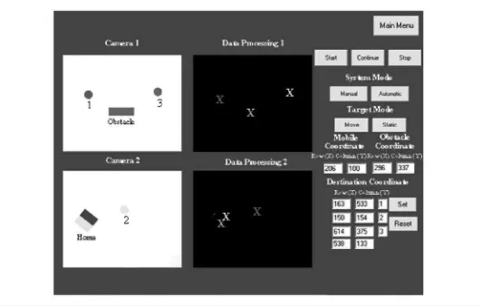
user could monitor the activity the robot in control room. The details of the mobile robot activity on screen layout is shown in Figure 11.
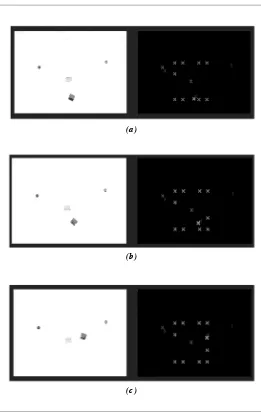
During the experiment, the destinations are represented in
red, obstacle in green and in-front and back-front of mobile robot in blue and pink color represented by X symbols. The X symbol in yellow color is the mobile robot target destination to be reached. The other destinations are represented by X symbol
in red color until the irst target is achieved. The destination
could be static or dynamic (moveable) and has been selected by the user. In this system, the overall data processing such as the objects coordinate are display at Figure 11.
Here the focus is on 2-D environment where the positions
of objects are represented in row and column (x, y). The 2-D
environment is more suitable because the cameras are mounted at their own stand camera and the images are taken from the cameras with one view called the top view. From the top view,
consider that, the Z-axis is zero and the X and Y-axis are
the position of the objects. The system only needs the position of the objects in the 2-D environment enough for it to get them.
In order to test the object classiication algorithm irst we
created a local color models on the grey histograms value of the
objects. Local color models were produced from the saturated hue values which have been collected during object classiication process. The detail about the classiication process is shows in
Figure 12.
During the obstacle avoidance challenges, a mobile robot has to move as quickly as possible from one destination to the other without hitting the obstacle. Some assumptions was make in the region of interest (ROI) in order to make avoidance is
completely done by setting the actual obstacle boundary 4 pixels
larger from the real size. By setting the obstacle boundary, the mobile robot has enough space to pursue to the avoidance points without touching the obstacle. Figure 13 shows how the mobile robot avoids the obstacle.
6.0 concLuSion
Based on the results in mobile robot activities screen layout at Figure 12, the fuzzy logic approach for controlling a mobile robot in intelligent space were presented. The system comprises
(a)
(b)
(c)
(a) (b)
(c) (d)
Figure 12 : the sample image indicated on how mobile robot avoids the obstacle
reFerence
[1] Wai-Lun, D.,L., Rangsarit, V., Zheng, L., Le, X., Tyler,
R., and Bulent, A. (2005). Intelligent Space with Time Sensitive Applications. North Carolina State University, Raleigh, USA.
[2] Hideki, H. (2004). Intelligent Space for Secure and Active
Humans’ Life. Institute of Industrial Science, University
of Tokyo
[3] Trevor, T. (2003). Collaborative Map Building by
Autonomous Robots using Visual Landmarks. Faculty
of Information Technology. Queensland University of Technology, Australia.
[4] PerS and KovaEiE. (2002). Computer Vision System for Tracking Players in Sports Games. Faculty of Electrical
Engineering, University of Ljubljana.
[5] Ching, H.K, and Wen, H.T. (2001). Obstacle Avoidance
in Person Following for Vision-Based Autonomous Land Vehicle Guidance Using Vehicle Location Estimation and Quadratic Pattern Classiier. Dept. of Computer and
Information Science. National Chiao Tung University, Taiwan.
[6] Khatib,O. (1986). Real-Time Obstacle Avoidance for Manipulators and Mobile Robots. The International Journal of Robotics Research, 5(1).
[7] Stefan, M., Roland, O., and Gregor, N. (2001). A Real-time Image Recognition System for Tiny Autonomous Mobile Robots, Institute of Computer Technology, Vienna Univ. of Technology.
[8] Martin, M. C. (2001). Visual Obstacle Avoidance Using Genetic Programming: First Results. Paper presented at the Genetic and Evolutionary Computation Conference (GECCO).
[9] Panagiotis, G.Z., Spyros, G.T., and Althoefer, K. (2000). Fuzzy Obstacle Avoidance and Navigation for Omnidirectional Mobile Robots. Dept. of Electrical and Computer Engineering. National Technical University of Athens.
[10] Joo-Ho, L., Kazuyuki, M., and Hideki, H.(2002). Mobile
Robot Control in Intelligent Space for People Support. Institute of Industrial Science, University of Tokyo, 4-6-1, Komaba, Meguro-ku, Tokyo, 153-8505 Japan, Journal of Robotics and Mechatronics, Vol.14, No.4 pp. 390-399, 2002
[11] Colin, V., and Crowley, J. L. (2000).Local Appearance Space for Recognition of Navigation Landmarks, Robotics
and Autonomous Systems, Vol 31, No 1-2, pp 61-70
[12] Joo-Ho, L., Noriaki ,A., and Hideki,H.(2000). Mobile
Robot Architecture in Intelligent Space. Institute of Industrial Science, University of Tokyo, 7-22-1 Roppongi, Minato-ku, Tokyo 106-8558, Japan, Journal of Robotics and Mechatronics, Vol.11, No.2 pp. 165-170, 2000
[13] Földesy, Szatmári and Zarándy. (1993). Moving Object Tracking on Panoramic Images. Hungary Computer and Automation Research Institute of the Hungarian Academy of Sciences (MTA-SZTAKI).
[14] Moore,D. (2003). A Real-World System for Human Motion Detection and Tracking. California Institute of Technology
[15] Nick, B., and Zhi-Qiang, L. (2002). Knowledge-based
vision-guided robots. Germany, A Sringer-Verlag Company.
[16] Alongkorn, V., Boonchana, P., Pitikhate, S., and Guanrong, C. (2002). Fuzzy Control for Soccer Robots. Dept. of Information Engineering. King Mongkut’s Institute of
Technology Ladkrabang, Thailand.
[17] Yutaka, J. K. (1994). Two Dimensional Wheeled Vehicle Kinematics. Dept. of Computer Science. Naval School, Monterey
[18] Birgit, K., and Dietmar. (2004). Fuzzy Modeling of Mobile Autonomous Soccer-Playing Robots-An Education
approach With LEGO Mindstorms Robots. Arbeitsbereich
Technische Informatiksysteme, Hamburg.
of three algorithms they are object classiication, object tracking
and obstacle avoidance. The goal of this project is to “teach” and “train” the mobile robot pursuing to the destinations where the destination are represents in ball with different colors without colliding with any obstacle. The intelligent part of this system is that the system can detected and track the objects either in static or dynamic (moveable). Besides, all the positions are displayed on the monitor screen in a control unit room with different colors by X symbols.
The system is totally based on a vision system with two cameras which replace need for sensors. Without sensors the system still can detect or identify the obstacle by using cameras. Besides that, the cameras also can identify and classify the objects in terms of objects area on local color models.
AcKnowLedgMent
[19] Weimin, S., and Jason, G. (2001). Fuzzy Approach For Mobile Positioning. Dept. of Electrical and Computer Engineering. Dalhousie University, Canada.
[20] Yutaka, J. K. (1997). “Rotary Vehicle” That Moves with Three Degrees of Freedom. Dept. of Computer Science. Naval School, Monterey
[21] Yujin Robotic. (2000). A Manual for Robot Soccer YSR-A 5vs5 Systems (Meteor 2/4 type). Korea, Yujin Robotic
Co., Ltd.
proFiLeS
Syed nAjib bin Syed SALiM
Syed Najib bin Syed Salim was born in Kuala Lumpur, Malaysia in 1973. He received his secondary
education from Sekolah Menengah Tengku Mahkota, Muar, Johor. He received his Diploma (Electric-Communcation) from Universiti Teknologi Malaysia in 1991, B.Eng. (Mechatronics) from Universiti Teknologi Malaysia in 1998. He completed his M. Eng. (Electrical) at Universiti Teknologi Malaysia in 2003. Currently he is a lecturer at the Universiti Teknikal Malaysia Melaka, Air Keroh Melaka. His primary interests are control systems and power electronic and drive.
hAiroL nizAM bin Mohd. ShAh
Hairol Nizam bin Mohd. Shah was born in Melaka, Malaysia in 1979. He received his secondary education from Sekolah Menengah Seri Mahkota Umbai, Melaka. He received his Diploma (Electric-Electronic) from Universiti Teknologi Malaysia in 2000, B.Eng. (Electric-(Electric-Electronic) from Universiti Malaysia Sabah in 2004. He completed his M. Eng. (Electrical) at Universiti Teknikal Malaysia Melaka in 2008. Currently he is a lecturer at the Universiti Teknikal Malaysia Melaka, Air Keroh Melaka. His primary interests related to vision systems and image processing.
MArizAn bin SuLAiMAn
Marizan bin Sulaiman was born in Kuala Besut, Terenganu, Malaysia in 1962. He received his secondary education from Maktab Rendah Sains Mara, Seremban. He obtained his B.Sc., M.E.E. and Ph.D. in Electrical from Universiti of Missouri-Columbia (UMC), USA in 1984, 1985 and 1989. He has been lecture at Universiti Sains Malaysia from 1990-2002 and currently is the Dean of Fakulti Kejuruteraan Elektrik at Universiti Teknikal Malaysia Melaka since 2002. Prof. Dr Marizan has written over 5 book, 9 modules and 50 technical papers for various journals and conferences. His research
interests including all area of power systems, energy eficient systems, control and instrumentation