‘Saya akui bahawa telah membaca
karya ini dan pada pandangan saya / kami karya ini
adalah memadai dari segi skop dan kualiti untuk tujuan penganugerahan Ijazah Sarjana Muda Kejuruteraan Mekanikal (Rekabentuk dan Innovasi)’
Tandatangan :………
Nama Penyelia : En. Omar bin Bapokutty
“Saya akui laporan ini adalah hasil kerja saya sendiri kecuali ringkasan dan petikan yang tiap-tiap satunya saya telah jelaskan sumbernya”
Tandatangan : ………..
To my beloved family,
ACKNOWLEDGEMENT
I would like to express an immense gratitude to the God Al-Mighty Allah s.w.t and the true idol of ours, Rasulullah s.a.w. who gave me the will to pursue this report until it finished, the courage to hold on to my thoughts, and the astuteness to think wisely whenever I need it the most. I also want to dedicate a special appreciation to my parents whose always stand by my side and keep encouraging me until the end of whatever I am doing.
Special thanks to my respected lecturers Mr. Omar bin Bapokutty for his ideas and agreeable of making this report as something can be touched and observed physically, not just being expressed by speeches. His guidance, experiences and method of teaching were really useful for me in the future and I definitely think that it will somehow affect my opinion in a very positive way, indeed.
ABSTRAK
ABSTRACT
CONTENTS
CHAPTER TITLE PAGE
CONFESSION ii
DEDICATION iii
ACKNOWLEDGEMENT iv
ABSTRAK v
ABSTRACT vi
CONTENTS vii
LIST OF TABLES x
LIST OF FIGURES xii
LIST OF SYMBOLS xvi
LIST OF APPENDIXES xviii
CHAPTER I INTRODUCTION 1
1.1 An Overview on Analysis 1
1.2 Objective and Approach 2
1.3 Scope of Analysis 3
CHAPTER II LITERATURE REVIEW 4
2.1 Overview on Fracture Toughness 4
2.2 Carburization 11
2.4 Research Done For the Effect of Fracture Toughness
19
CHAPTER III METHODOLOGY 21
3.1 Introduction 21
3.2 Specimen preparation 23
3.3 Notch Tips Cutting Process 28
3.4 Carburizing 29
3.5 Testing Method for Compact Tension
30
CHAPTER IV RESULTS 34
4.1 Tensile Test 34
4.2 Fatigue Pre-Cracking Test 38
4.3 Fracture Toughness Test 40
CHAPTER V DISCUSSION 50
5.1 Introduction 50
5.2 Fracture Toughness 50
5.3 Factor Affecting The Results of Tensile Test, Fatigue Pre-Cracking Test and Fracture Test
53
5.4 Key factors In Performing fracture Toughness Test
54
CHAPTER VI CONCLUSION 55
REFERENCES 41
BIBLIOGRAPHY 42
LIST OF TABLES
NO. TITLE PAGE
2.1 Typical Fracture-Toughness Values for Selected Engineering Alloys
(Source: R.W. Herzberg, 1989)
5
2.2 Types of Carbon Steel
(Sources : www.wikipedia.com)
18
3.1 Specific value for a/W of Compact Specimens (Source: ASTM E399,1997)
33
4.1 Results for loads of tensile test (Un-carburized specimens)
35
4.2 Results for loads of tensile test (Un-carburized specimens)
36
4.3 Comparisons of Tensile Test results between carburized and un-carburized specimens
38
4.4 Comparisons of Fatigue pre-cracking test results between carburized and un-carburized specimens
4.5 Table of fracture toughness for un-carburized Low Carbon Steel
48
4.6 Table of fracture toughness for carburized Low Carbon Steel
LIST OF FIGURES
NO. TITLE PAGE
2.1 Load types for Modes of Fracture (Source: R.J Sanford, 2003)
5
2.2 Stress-strain behavior of Carbon Steel (Source: NDT Resource Center, 2001)
7
2.3 Types of Fracture Toughness Specimen (Source: P. Henryk, 2004)
9
2.4 Criteria of plain-stress and plain-strain (Source: N.E. Dowling, 1993)
10
2.5 Orientation of crack plane in fracture toughness (Source: ASTM E399, 1997)
11
2.6 Common method of carburizing 13
2.7 Case depth vs. carburizing time (Source: S.Z. Elgun, 1999)
2.8 Pack Carburizing Process (Source: Serdar Z. Elgun, 1999)
17
2.9 Illustration of Charpy and Izod Impact Tests. (Source: Callister W.D. Jr, 1994.)
20
3.1 Methodology of Analysis 22
3.2 Compact Specimen C (T) Standard Proportions (Source: ASTM E399, 1997)
23
3.3 (a) Scantool 254vsh Model Bandsaw Machine 24
3.3 (b) Cutting process using Bendsaw Machine 24
3.4 Haas CNC Milling Machine 25
3.5 Facing cut process using CNC Milling Machine 25
3.6 Specimen surface after squaring process 25
3.7 (a) Facing Cut 26
3.7 (b) Holes grinding 26
3.7 (c) Specimen after facing cut and grinding process 27
3.7 (d) Constraint measured to make sure specimen dimension follow the standard dimension.
3.7 (e) All 12 specimens after finish cutting process 27
3.8: Dimension for Notch Tips 28
3.9 EDM Wirecut Machine 28
3.10 Pack carburizing process flow 29
3.11 Tension Testing Clevis 31
3.12 Universal Tensile Machine 31
4.1 Graph of Tensile Test for Compact Specimen (Un-Carburized)
34
4.2 Un-carburized specimen condition after tensile test 35
4.3 Graph of Tensile Test for Compact Specimen (Carburized)
36
4.4 Carburized specimen condition after tensile test 37
4.5 Un-carburized specimens after fatigue pre-cracking test and ready for fracture toughness test.
39
4.6 Graph of fracture toughness for un-carburized specimen #1
41
4.7 Graph of fracture toughness for un-carburized specimen #2
4.8 Un-carburized specimens after fracture toughness test 42
4.9 Compact Specimen (CT) Standard Proportions (Source: ASTM E399, 1997)
42
4.10 Graph of fracture toughness for carburized specimen 1 45
4.11 Graph of fracture toughness for carburized specimen 2 45
4.12 Carburized specimens after fracture toughness test 46
5.1 Specimens after fracture toughness 51
5.2 Comparison of curves for ductile and brittle materials: (a) ductile material; (b) brittle material
(Source: J.W. Fisher, 1984)
52
5.3 Result of tensile test: (a) un-carburized specimen; (b) carburized specimens
52
LIST OF SYMBOLS
a = Crack Length, mm
B = Specimen Thickness, mm
E’ = Effective Young’s Modulus, Pa (psi)
KI = Stress Intensity Factor, MPa.m1/2
KIC = Plane-Strain Fracture Toughness, MPa.m1/2
KIC (t) = Rapid Load Plane-Strain Fracture Toughness, MPa.m1/2
KQ = Fracture Toughness, MPa.m1/2
P = Specific Load, klbf (kN)
Pmax = Maximum load that specimen able to sustain, klbf (kN)
RSC = Specimen Strength Ratio
Tx = Temperature of Rapid Load Toughness Test, K
Vm = Crack Mouth Opening Displacement, mm = Poisson Ratio
F = Fracture Stress, MPa
YD = Dynamic Yield Strength, MPa
YS = Yield Strength, MPa
LIST OF APPENDICES
NO. TITLE PAGE
A ASTM Standard Related to Fracture Mechanics 59
B Standardized codes for specimen configurations and applied load
60
C Principal Types of Load-Displacement Records 61
D Fractograph of ductile cast iron showing a transgranular fracture surface
62
E Fractograph of an intergranular fracture surface 63
1
CHAPTER I
INTRODUCTION
1.1 An Overview on Analysis
This thesis systematically investigates the effect on fracture toughness of
Low Carbon Steel with and without carburizing. In order to run the analysis and
from the previous research done, Carbon Steel; type AISI 1020) is the most suitable
material that can be used for the testing to get the result. By using compact specimen
followed with ASTM standard, testing will be conducted in two conditions; with and
without carburization. Using ASTM E399 as a guide, Plane Strain Fracture
Toughness experiment using compact specimen will be carried out in order to obtain
the necessary information for the analysis.
In materials science, fracture toughness is a property which describes the
ability of a material containing a crack to resist fracture, and is one of the most
important properties of any material for virtually all design applications. It is
denoted as K1c.The subscript '1c' denotes mode 1 (crack opening; ordinary strain),
since the material can be made thick enough to resist shear (mode 2) or tear (mode
3). Fracture toughness is a quantitative way of expressing a material's resistance to
brittle fracture when a crack is present. If a material has a large value of fracture
toughness it will probably undergo ductile fracture. Brittle fracture is very
2
Fracture occurs when the metal experiences stress that exceeds its yield
strength. Fractures occur as two different types, ductile fracture and brittle fracture.
Brittle fracture occurs when the metal doesn’t yield before it breaks. Instead of the
sheets of atoms in the metal sliding over each other as occurs in deformation, when
stressed, the sheets of atoms pull completely apart. This type of fracture most often
occurs in metals that are extremely hard. Brittle fracture almost always occurs at low
temperatures. Ductile fracture is the most common type of fracture in metal. Unlike
what occurs in a brittle fracture, the metal yields before it breaks in a ductile
fracture. The peak stress a metal can withstand before it breaks is called tensile
strength. Ductile fracture is caused by the stress exerted on the metal actually work
hardening the metal as it yields, cracks from fatigue develop, and then these cracks
propagate very rapidly through the metal until complete failure occurs
1.2 Objective and Approach
The main objectives of this analysis are:
I. To analyze the effect on fracture toughness on Low Carbon Steel in two
condition; (1) with carburizing and (2) without carburizing.
II. To compare the effect on fracture toughness between carburizing and
without carburizing.
The fracture toughness testing procedures specified in ASTM Standard No.
E399 will be used. Ten compact specimens of nominal thickness 25mm will be
tested. Each sample contains a notch, or 'machined crack'. At the tip of the notch a
3
1.3 Scope of Analysis
In this analysis, there are three major scopes needs to be considered in order
to achieve the objectives of analysis.
Specimen preparation is the first step of analysis. There will be 10 specimen
needs to be prepared for this analysis. Dimensions and tolerances of the specimen
will be followed by ASTM Standard for compact specimen dimension. Material that
will be used for this analysis is AISI 1020 carbon steel that is the most suitable
specification of low carbon steel.
Carburizing process of the specimen will be conducted before the testing.
Only five (5) specimens will be carburized for testing while another five (5)
specimens will be used without carburizing. The method of carburizing will be
conducted using pack carburization method.
Testing method will be conducted using ASTM Standard Test Method for
Plain-Strain Fracture Toughness. Testing will be conducted in two different
conditions; (1) without carburizing, and (2) with carburizing. Then the result on both
4
CHAPTER II
LITERATURE REVIEW
2.1 Overview on Fracture Toughness
Fracture toughness is an indication of the amount of stress required to
propagate a preexisting flaw. It is a very important material property since the
occurrence of flaws is not completely avoidable in the processing, fabrication, or
service of a material/component. Flaws may appear as cracks, voids, metallurgical
inclusions, weld defects, design discontinuities, or some combination thereof. Since
engineers can never be totally sure that a material is flaw free, it is common practice
to assume that a flaw of some chosen size will be present in some number of
components and use the linear elastic fracture mechanics (LEFM) approach to
design critical components. This approach uses the flaw size and features,
component geometry, loading conditions and the material property called fracture
toughness to evaluate the ability of a component containing a flaw to resist fracture.
(from NDT Resource Center, 2001)
A parameter called the stress-intensity factor (K) is used to determine the
fracture toughness of most materials. A Roman numeral subscript indicates the
mode of fracture and the three modes of fracture are illustrated in Figure 2.1. Mode I
fracture is the condition in which the crack plane is normal to the direction of largest
tensile loading that is indicates testing in which a tensile stress causes the crack to
open. This is the most commonly encountered mode and, therefore, for the
remainder of the material will be consider as KI (refer
5
Mode-I Stress intensity factor, KIc is the most often used engineering
design parameter.
Mode-II Opening or tensile mode where the crack surfaces move directly apart.
Mode-III Tearing and anti-plane shear mode where the crack surfaces move relative to one another and parallel to the leading edge of the crack.
[image:23.612.138.506.84.197.2]
Figure 2.1: Load types for Modes of Fracture
[image:23.612.129.522.457.685.2](Source: R.J Sanford, 2003)
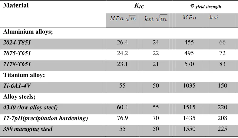
Table 2.1: Typical Fracture-Toughness Values for Selected Engineering Alloys
(Source: R.W. Herzberg, 1989)
Material KIC yield strength
Aluminium alloys;
2024-T851 26.4 24 455 66
7075-T651 24.2 22 495 72
7178-T651 23.1 21 570 83
Titanium alloy;
Ti-6A1-4V 55 50 1035 150
Alloy steels;
4340 (low alloy steel) 60.4 55 1515 220
17-7pH(precipitation hardening) 76.9 70 1435 208
6
Fracture toughness values of material are most useful in mechanical design
when working with materials of limited toughness or ductility such as high-strength
aluminum, steel and titanium alloys. Table 2.1 lists KIC values for some of these
alloys. Material that show little plastic deformation before fracture have relatively
low fracture toughness, KIC values and tend to be more brittle, whereas those with
higher KIC values are more ductile. Fracture toughness values can be used in
mechanical design to predict the allowable flaw size in alloys with limited ductility
acted upon by specific stresses. (from R.W. Herzberg, 1989)
2.1.1 Toughness
The ability of a metal to deform plastically and to absorb energy in the
process before fracture is termed toughness. The emphasis of this definition should
be placed on the ability to absorb energy before fracture. Recall that ductility is a
measure of how much something deforms plastically before fracture, but just
because a material is ductile does not make it tough. The key to toughness is a good
combination of strength and ductility. A material with high strength and high
ductility will have more toughness than a material with low strength and high
ductility. Therefore, one way to measure toughness is by calculating the area under
the stress strain curve from a tensile test. This value is simply called “material
toughness” and it has units of energy per volume. Material toughness equates to a