ANALYSIS AND MEASUREMENT OF OPTICAL FIBER CHANNEL DOUBLER (OFCD)
ABDUL AZIZ BIN ROZI
This report is submitted in partial fulfillment of the requirement for the award of Bachelor of Electronic Engineering (Telecommunication Electronics)
With Honors
Faculty of Electronic and Computer Engineering Universiti Teknikal Malaysia Melaka (UTeM)
ii
UNIVERSTI TEKNIKAL MALAYSIA MELAKA
FAKULTI KEJURUTERAAN ELEKTRONIK DAN KEJURUTERAAN KOMPUTER
BORANG PENGESAHAN STATUS LAPORAN
PROJEK SARJANA MUDA II
Tajuk Projek ANALYSIS AND MEASUREMENTS OF OPTICAL FIBER
CHANNEL DOUBLER (OFCD)
Sesi
Pengajian 0 9 / 1 0
Saya ABDUL AZIZ B ROZI
(HURUF BESAR)
mengaku membenarkan Laporan Projek Sarjana Muda ini disimpan di Perpustakaan dengan syarat-syarat kegunaan seperti berikut:
1. Laporan adalah hakmilik Universiti Teknikal Malaysia Melaka.
2. Perpustakaan dibenarkan membuat salinan untuk tujuan pengajian sahaja.
3. Perpustakaan dibenarkan membuat salinan laporan ini sebagai bahan pertukaran antara institusi
pengajian tinggi.
4. Sila tandakan ( ) :
SULIT*
*(Mengandungi maklumat yang berdarjah keselamatan atau kepentingan Malaysia seperti yang termaktub di dalam AKTA RAHSIA RASMI 1972)
TERHAD**
**(Mengandungi maklumat terhad yang telah ditentukan oleh organisasi/badan di mana penyelidikan dijalankan)
TIDAK TERHAD
Disahkan oleh:
__________________________ _______________________________
(TANDATANGAN PENULIS) (COP DAN TANDATANGAN
iii
DECLARATION
“I hereby declare that this report is result of my own effort except for works that have been cited clearly in the references.”
Signature : ………. Name : ....……….
Date : ……….
iv
SUPERVISOR APPROVAL
“I hereby declare that I have read this report and in my opinion this report is sufficient in terms of scope and quality for the award of Bachelor of Electronic
Engineering (Telecommunication Electronics) with Honours”
Signature : ……….
Supervisor’s Name : ....……….
Date : ……….
v
DEDICATION
To my beloved father and mother &
My sisters
For your infinite and unfading love, sacrifice, patience, encouragement and Best wishes
vi
ACKNOWLEDGEMENT
In the name of Allah, the Most Beneficent, the Most Merciful. First and foremost, all praise to Allah for the incredible gift endowed upon me and for give me the health and strength to enable me finish this thesis towards the right track.
I would like to express my gratitude towards my supervisor Mr. Chairulsyah B Abdul Wasli who helped me a lot in guiding me and the advices given from him in the course of this project. May the sky be your limits for your endeavour.
Also, I would like to thank my lovely parents who always supported me from behind for not given up hope in completing this project report. A wish of thanks also to Prof. Dr. Mohd. Adzir Mahdi for helping hands giving tips in using Optisystem Software.
Finally, i would like to thank Mr Aziz Ramli, Mr Yousri Taibin and Mr Naim from Sigtech Sdn Bhd for allowing me visit the company to do measurements as well as the permission to use the OFCD which most important in this project. Without their help, this project may be unsuccessful. Thank you very much.
vii
ABSTRAK
Projek ini dianalisa dan direka untuk mengkaji komunikasi dua arah dalam satu masa yang sama. Dalam projek ini, komponen utama yang digunakan yang berperanan penting ialah OFCD. Komponen-komponen lain dalam komunikasi optik juga dianalisa supaya ianya bersesuaian dalam rekabentuk komunikasi dua arah dimana jumlah kehilangan kuasa diambil kira. Isyarat pantulan yang dihasilkan oleh system ini juga dianalisa. Cakap-silang jalur-inter dan jalur-intra di model dan di analisa di dalam sistem ini. Peningkatan nilai cakap-silang jalur-intra akan menyebabkan peningkatan dalam nilai kuasa tendangan. Sekiranya keadaan ini berlaku nilai kuasa tendangan akan dikira. Pengiraan juga dilakukan bilamana hingar didominasi oleh hingar terma. Keputusan yang diperolehi menunjukkan nilai kuasa tendangan merosot teruk. Untuk mencegah nilai cakap-silang daripada berlaku, penambahan jalur diantara saluran yang hendak dihantar mestilah mematuhi ITU-T piawaian.
viii
ABSTRACT
The report is prepared from the point of view of designing a bidirectional communication link using OFCD. The various components required for the link are discussed here. Also the performance of the link in terms of the loss penalty and the various types of noise produced is also considered. The bidirectional link using OFCD had been studied in terms of the total loss introduced while constructing the link and the loss margin available using the components. The interference caused or the degradation of the forward signal due to the superposition of the other returning signal is taken into consideration. The crosstalk were modeled and analyzed. The power penalty also was calculated. Calculation was also made to calculate the BER, determination of receiver sensitivity that suits bidirectional link. It was found that the power penalty is worst for the thermal noise dominated case. The gain band between the channels to be transmitted should be according to the ITU-T standards to prevent crosstalk from occurring.
ix
LIST OF CONTENTS
CHAPTER TITLE PAGE
PROJECT TITLE i
DECLARATION ii
SUPERVISOR APPROVAL iii DEDICATION iv
ACKNOWLEDGEMENT v
ABSTRAK vi
ABSTRACT vii
LIST OF CONTENTS viii
LIST OF TABLES xii
LIST OF FIGURES xiv
LIST OF ABBREVIATIONS xvi
I INTRODUCTION 1
1.1 PROJECT BACKGROUND 1
1.2 PROBLEM STATEMENTS 2
1.3 PROJECT OBJECTIVES 3
1.4 SCOPE OF WORKS 3
1.5 PROJECT METHODOLOGY 4
1.6 EXPECTED OUTCOMES 5
II LITERATURE REVIEW 6
2.1 INTRODUCTION 6
2.2 BACKGROUND STUDY 7
2.3 OPTICAL FIBER COMMUNICATION TECHNOLOGY 8
x
2.3.2 Bidirectional Transmission Link 9 2.4 COMPONENTS USED IN THE LINK 11
2.4.1 Transmitter 11
2.4.1.1Laser Type 11
2.4.2 Optical Fiber Channel Doubler (OFCD) 13 2.4.2.1Optical Isolator 14 2.4.2.2Optical Circulator 15 2.4.2.3Optical Circulator Specifications 17
2.4.3 Optical Fiber 18
2.4.4 Connector 18
2.4.4.1Optical Return Loss 18
2.4.5 Receiver 19
2.5 10 GB/s 150 BIDIRECTIONAL REPEATERLESS OPTICAL FIBER TRANSMISSION 19 2.6 CROSSTALK LIMITED TRANSMISSION DISTANCE IN BIDIRECTIONAL FIBER
OPTIC SYSTEMS 23
III RESEARCH METHODOLOGY 27
3.1 INTRODUCTION 27
3.2 DATA COLLECTION 27
3.3 PROJECT PLANNING 28
3.4 SIMULATION LINK DESIGN
CONSIDERATION 29
3.4.1 Light Source 29
3.4.2 Bidirectional Optical Circulator 30 3.4.3 Bidirectional Optical Fiber Cable 31
3.4.4 Optical Detector 31
3.4.5 Bit Sequence Generator & Pulse Generator 32
3.4.6 Spectrum Analyzer 33
3.4.7 Bidirectional Link Design 33 3.4.7.1Power Measurements 33 3.4.7.2Crosstalk Measurements 34
xi
3.5 MEASUREMENT LINK DESIGN
CONSIDERATION 35
3.5.1 Power Measurements 38 3.5.2 Bit Error Rate (BER) Test 39 3.6 DIGITAL SYSTEM PLANNING
CONSIDERATION 40
3.6.1 Optimum SNR Value 40
3.7 SYSTEM CROSSTALK 46
3.7.1 Power Penalty due to Crosstalk 46 3.7.2 System Power Penalty 49 3.7.3 Wavelength Separation Between Channel 49
3.8 SYSTEM DISPERSION 50
3.9 INSERTION LOSS 52
3.9.1 Determination of Ideal Insertion Loss 53
3.10 ISOLATION 54
3.11 RETURN LOSS 54
3.12 SIGNAL TO NOISE RATIO (SNR) 55
3.13 BIT ERROR RATE (BER) 57
3.14 OPTICAL POWER BUDGET 58
IV RESULT 61
4.1 CALCULATION RESULTS 61
4.1.1 Insertion Loss 61
4.1.2 Isolation 63
4.1.3 Return Loss 65
4.1.4 Comparison 66
4.1.5 Power Received of the Link 67 4.1.6 Power Received due to Variation of Link
Length 68
4.1.7 Optical Communication System Power
Budget 70
4.1.8 Maximum Possible Link Length 73 4.1.9 Power Penalty due to Crosstalk Coupling
Coefficient 73
xii
4.1.10 Signal to Noise Ratio and Bit Error Rate 76
4.2 SIMULATION RESULTS 79
4.2.1 Power Measurements 79
4.2.1.1Power Measurements at each Port 79 4.2.1.2Power Measurements at each Device 81 4.2.2 Optical Signal Spectrum Observations 83 4.2.2.1Critical Condition 87 4.2.3 Miscellaneous 89
4.3 MEASUREMENT RESULTS 90 4.3.1 Power Measurements at each Port of OFCD 90
4.3.2 Power Measurements Bidirectional Link Design Consideration 92
4.3.3 Bit Error Rate (BER) Test 93 4.3.4 Optical Signal Spectrum Observations 95 V CONCLUSION 96
5.1 DISCUSSION 96
5.2 CONCLUSION 97
5.3 FUTURE WORKS 98
REFERENCES 99
APPENDIX A 101
APPENDIX B 102
APPENDIX C 103
APPENDIX D 104
APPENDIX E 105
APPENDIX F 106
xiii
LIST OF TABLES
NO TITLE PAGE
2.1 Parameters of Three-port Optical Circulator 17
4.1 Comparison of Insertion Loss, Return Loss, and Isolation 67
4.2 Power received due to variation of link length at Rx2 69
4.3 Power received due to variation of link length at Rx1 69
4.4 System Power Budget Calculation 71
4.5 Loss Margin for Variable of Link Length 72
4.6 Power Penalty due to Crosstalk Coupling Coefficient for 75
Various Link Length 4.7 The relationship between power received, SNR, and BER 78
4.8 Power Measurements at each Port of OFCD 1 81
4.9 Power Measurements at each Port of OFCD 2 81
4.10 Power transmitted from Tx1 83
4.11 Power transmitted from Tx2 83
4.12 Simulation Results of OSA 2 for the Link length of 40km 86
4.13 Simulation results of OSA 1 for link length of 40km 87
4.14 Measurement of Noise, OSNR, and Dispersion for Tx1 89
4.15 Measurement of Noise, OSNR, and Dispersion for Tx2 89
4.16 Power Measurements at each Port of OFCD 1 91
4.17 Power Measurements at each Port of OFCD 2 91
4.18 Power transmitted from Transmitter 1 92
4.19 Power transmitted from Transmitter 2 92
xiv
LIST OF FIGURES
NO. TITLE PAGE
1.1 Block Diagram of Duplex Optical Communication using Optical 2
Fiber Channel Doubler (OFCD) 1.2 Project Flowchart 4
2.1 Simplex Transmission System using Two Fiber Cables 9
2.2 Bidirectional Transmission Link using OFCD 10
2.3 FWHM of Fabery-Perot Laser 12
2.4 FWHM of DFB Laser 12
2.5 DFB Laser 13
2.6 Principles of Optical Isolator 14
2.7 Three-port and four-port Optical Circulator 15
2.8 Basic Operation of Three-port Circulator 16
2.9 Light beam entering at Port 2 will exit from Port 3 16
2.10 Bidirectional transmission system 20
2.11 Bit error rates curves for different unidirectional system 21
configurations at 1557.7nm 2.12 Bit error curves for both systems over 125km of DSF at 1553.3nm 22
2.13 schematic block diagram of experimental setup 23
2.14 results of bit error rate as a function of interference power for 24
representative signal level. 2.15 Power penalty in the presence of interference “crosstalk” 25
2.16 Schematic diagram of full duplex system. 26
3.1 Gantt Chart for PSM 1 and PSM 2 28
3.2 Optical Light Source (CW Laser) 29
xv
3.4 OFCD 2 at Transceiver 2 30
3.5 Bidirectional Optical Fiber Cable 31
3.6 Optical Delay and Optical Null 31
3.7 Photodetector APD 31
3.8 PRBS and NRZ Pulse Generator 32
3.9 Mach-Zender Modulator 32
3.10 OSA and RFSA 33
3.11 Bidirectional Link Design considering measurements of optical 34
power 3.12 Bidirectional link design considering crosstalk measurements 35
3.13 Configuration measurement of insertion loss of OFCD 36
3.14 Configuration measurement of isolation of OFCD 36
3.15 Configuration of measurement of bidirectional link using OFCD 37
3.16 Bidirectional Link Design for Power Measurements 38
3.17 Power Measurements at each port 38
3.18 BER Test for Bidirectional Link 39
3.19 Fiber optic attenuation 50
3.20 Chromatic Dispersion per km vs. wavelength in (nm) 51
3.21 Dispersion effects 51
4.1 Graph of power penalty against crosstalk coupling coefficient 75
4.2 Power Measurements at each port of OFCD 1 80
4.3 Power Measurements at Each Port of OFCD 2 80
4.4 Power Measurements at each Device and Rx 2 82
4.5 Power Measurements at each Device and Rx 1 82
4.6 Simulation results of Optical Signal detected at Rx1 (a) 84
4.7 Simulation results of Optical Signal detected at Rx1 (b) 84
4.8 Simulation results of Optical Signal detected at Rx2 (a) 85
4.9 Simulation results of Optical Signal detected at Rx2 (b) 86
4.10 Intraband Crosstalk 88
4.11 Power measurements throughout port 2 of OFCD 90
4.12 power measurement to determine the isolation and return loss of 91
OFCD 4.13 BER Test for Signal detected at Rx 2 93
xvi
LIST OF ABBREVIATIONS
APC - Angle Polished Connectors
APD - Avalanche Photodiode Detector ASE - Amplified Spontaneous Emission
BER - Bit Error Rate
C – Band - Optical band from 1530 to 1570nm long
CW - Continuous Wave
CWDM - Coarse Wavelength Division Multiplexing
dB - Decibel
dBm - Decibel in miliwatt
DFB - Distributed Feedback
DSB - Double Side Band
DSF - Dispersion Shifted Fiber
DWDM - Dense Wavelength Division Multiplexing EDFA - Erbium Doped Fiber Amplifier
FB - Fabry Perot
FBG - Fiber Bragg Grating
FDM - Frequency Division Multiplexing
FWHM - Full Width Half Minimum
FWM - Four Wave Mixing
Gb/s - Gigabits per second
ITU - International Telecommunication Union
LD - Laser Diode
LED - Light Emitting Diode
NRZ - Non-Return to Zero
OADM - Optical Add Drop Multiplexer
OFCD - Optical Fiber Channel Doubler
ORL - Optical Return Loss
OSA - Optical Semiconductor Amplifier
xvii
OTDR - Optical Time Domain Reflectometer
PIN - Positive Intrinsic Negative
PMD - Polarization Mode Dispersion
PCM - Pulse Code Modulation
PRBS - Pseudo Random Bit Sequence
RFSA - RF Spectrum Analyzer
SDH - Synchronous Digital Hierachy
SMF - Single Mode Fiber
SNR - Signal-to-Noise Ratio
SONET - Synchronous Optical Network
SOP - State of Polarization
SPM - Self Phase Modulation
STM - Scanning Tune Microscope
SWP - Spatial Walk-off Polarization
TDM - Time Division Multiplexing
WDM - Wavelength Division Multiplexing
XPM - Cross Phase Modulation
CHAPTER I
INTRODUCTION
1.7 PROJECT BACKGROUND
2
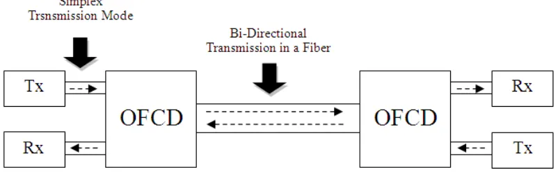
[image:19.612.144.545.235.359.2]stage of this project. This project wills analysis the OFCD from the theoretical and measurement aspects. Also find its advantages and disadvantages. The vast is study literature, design, simulate and test. This device actually had been used widely in today’s optical communication technology as a result of huge development of DWM and DWDM technology. Generally, simple communication uses two optical cables; transmit and receive, and vice versa. But the advantage of OFCD is the simplicity of transmission line whereby only one fiber cable used.
Figure 1.1: Block Diagram of Duplex Optical Communication using Optical Fiber Channel Doubler (OFCD)
The figure above shows the basic duplex communication link using OFCD whereby it uses only one cable fiber. This system is not as complex as usual transceivers system that uses two cable fiber.
1.8 PROBLEM STATEMENTS
Generally, optical communication involving unidirectional line in a fiber which makes up two optical fiber cables to make one connection. If there are many connections to be setup, there will be more cables used. This will increase the cost as the price of optical cable is expensive. To solve this problem, a new device was introduced named Optical Fiber Channel Doubler (OFCD).
3
cables for point to point communication is inefficient. This project will save 50% optic cable usage by using an OFCD device.
1.9 PROJECT OBJECTIVES
The objectives of this project that I had underlined are: i. To analyze the designation of OFCD device
ii. To measure all the parameters which convey the theoretical parts of OFCD iii. Theoretical study and analysis of duplex optical communication
iv. Simulation of duplex optical communication utilizing single fiber
1.10 SCOPE OF WORKS
4
the other hand, the optical power budget must be taken into consideration. The comparison also must be distinguished to show that OFCD is better device for full duplex transmission.
1.11 PROJECT METHODOLOGY
5
1.12 EXPECTED OUTCOMES
After the project had been done successfully, the possible outcomes would likely to be the followings:
i. The important parameters of Optical Fiber Channel Doubler (OFCD) as a device that allows transmitted and received signals in one fiber cable
ii. Animation that explains how OFCD works in bi-directional optical communication link
iii. Power measurements at each port of OFCD iv. Bidirectional link design using OFCD
6
CHAPTER II
LITERATURE REVIEW
2.6 INTRODUCTION
Literature review is important role of any projects as it is fundamental towards completion the research in accordance to gather the information whereas its necessity of a completed project. All the information is collected and studied thoroughly from several of source, such as:
i. Reference Books ii. Journals
iii. Thesis iv. Patents
v. Internet
vi. Conference Transcript
7
Optical Fiber Channel Doubler (OFCD). The information that is being filtered out will be compiled to be included in this report.
2.7 BACKGROUND STUDY
In any communication system used today, there are two main types of classification distinguished, they are “unidirectional and bidirectional” transmission links. In this project, it is more focused about bidirectional transmission system whereas two transmitted signals to be allowed in one fiber cable. This project also was focusing on the investigation of the possibility of increasing the capacity of transmitted data on bidirectional link.
The main role in this project is Optical Fiber Channel Doubler (OFCD), it plays the most important part in allowing two transmitted signal in one communication link. The device is now used widely in communication system as far as its simplicity for applying it to any types of communication link. With the existence of OFCD, communication system today become more straightforward as it reduces the cost of budget as well as power budget.
OFCD is actually made up of optical circulator which is a passive element that is widely used in the fiber optic system especially involving bidirectional link. The circulator can be used to decouple transmitted and received signals travelling along the same fiber [1].
An optical circulator is a special fiber optic component that can be used to separate powers that travel in opposite directions in one single optical fiber, analogous to the operation of an electronic circulator. An optical circulator is a three port device that allows light travel in only one direction. A further detail of the operations of circulator will be described more on the latter stage of this research report.