1
The Gasoline Direct Injection (GDI) requirement for special components had been limiting its wider implementation. This work was carried out to obtain an experimental GDI system for a small capacity two-stroke engine by using widely available Port Fuel Injection (PFI) components. A low-pressure GDI system where a PFI injector was placed in position near scavenging port had been obtained. The injection control system used throttle position and engine speed data to
determine the injection duration and the start of injection. The injection system’s fuel supply
characteristics was design to imitate the fuel supply characteristics of the engine’s carburetor that was previously measured by varying load at constant throttle openings. The mass flow rate measurement showed that the fuel injection system was able perform well at small throttle opening and low engine speed but it needed more improvement to operate better at other operating conditions.
Keywords: Fuel injection, injection control, GDI, low-pressure GDI, two-stroke gasoline engine
INTRODUCTION
Scavenging process is both the good and the bad parts of a conventional two-stroke gasoline engine design. The presence of scavenging process makes two-stroke engine able to expel residual combustion gas out and admit fresh fuel-air mixture in to the combustion chamber on just one piston stroke. During that same scavenging process however, some of the fresh mixture got
carried away to the exhaust manifold and thus making the engine’s fuel consumption and
emission characteristics worse than its four-stroke counterpart.
The advancement of electronic fuel injection technology had led to the development of Gasoline Direct Injection (GDI); a type of fuel injection technology in which fuel is being injected directly into the combustion chamber. By placing injector inside the combustion chamber, GDI technology provides more flexible injection-timing on the entire engine-operating conditions [9]. Injection timing can be set earlier during the intake stroke so that injection system can serve more homogeneous and rich mixture when the engine is operated under high load and speed conditions. The injection timing can also be set later during compression stroke so that the injection system can serve more stratified and lean mixtures when the engine is operated under low load and speed conditions.
provided by GDI technology is the presence of charge cooling effect obtained through the fuel
vaporization inside combustion chamber which will increase the engine’s volumetric efficiency
and reduce knocking [9]. The combined effect of the advantages of GDI technology had been proven to be able to deliver more economical fuel consumption and lower exhaust emission from four-stroke engine as well as two-stroke engine [1 - 7, 9].
Even with all the advantages that the GDI offers, its current application is limited only to the engine used in expensive cars or motorcycles. GDI technology demands better components than the available injection-components. This work aimed to study the potential of widely available Port Fuel Injection (PFI) components to be used in GDI system for a small capacity two-stroke gasoline engine.
EXPERIMENTAL SETUP
This research had been carried out on a water cooled, carbureted, and 148 cc two-stroke gasoline engine. The fuel consumption of the carbureted engine was measured by varying load and throttle opening to simulate the engine operating condition. The fuel consumption data were then used as fuel map data in fuel injection control program.
The fuel injector and its pump that were employed in the injection system, shown in Figure 1 (a) and (b), were parts of a PFI system originally used for a 150 cc four-stroke engine. The injector and pump were chosen based on the assumption that the combination will deliver the closest fuel flow rate needed by the engine.
(a) (b)
Figure 1. (a) The PFI injector being used in this research (mounted on the engine’s cylinder head), (b) the injector’s fuel pump
The injector response time and fuel flow rate of the injectors were measured in order to evaluate
their compatibility to the engine and injection system’s designed-operating-condition. The
injector response time data was obtained by placing accelerometer on the injector’s body and then
3 RESULT AND DISCUSSION
The Comparison between the PFI Injector Characteristics and the Engine’s Required Fuel Supply Characteristics
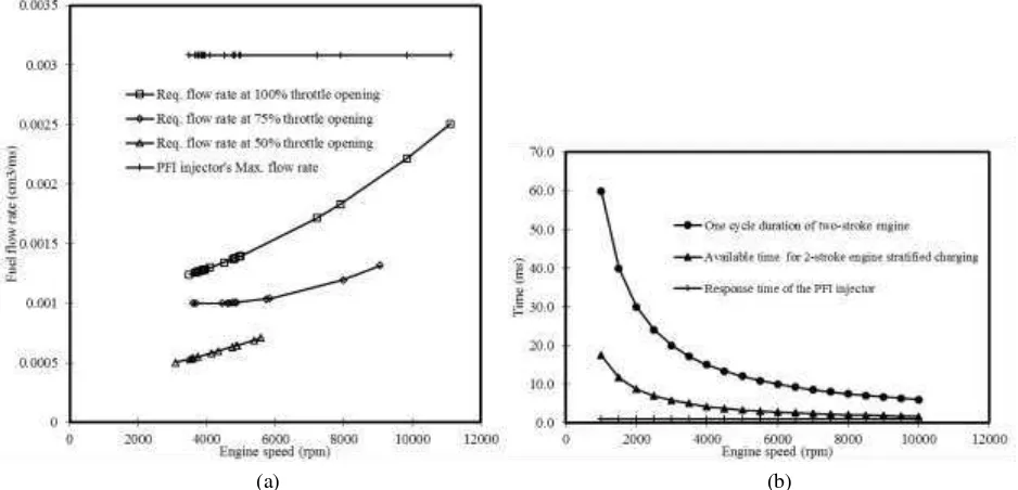
As can be seen in Figure 3 (a), the measured maximum fuel flow rate from the PFI injector was
3.08 cm3/second, high enough to supply the required engine’s fuel flow rate at 100, 75, and 50 %
throttle openings. The measured total response times (open and close) of the PFI injector was 1
ms. Figure 3 (b) shows the injector’s response time was shorter if compared to one cycle duration
of two-stroke engine and the available time for two-stroke engine stratified charging at various engine speed which was calculated by using exhaust and scavenging ports open and close timings data shown in Figure 4 (a) and (b).
(a) (b) .
Figure 3. (a) Maximum fuel flow rate of the PFI injector compared to required fuel flow rate at 100, 75, and 50 % throttle opening, (b) Injector’s total response-time compared to one cycle duration of two-stroke engine and time
available for two-stroke engine stratified charging at various engine speed
(a) (b) .
Ideally, injection should be done in period between the start of scavenging port closing and the start of ignition, shown in Figure 4 (b), when there is a little to none air flowing from scavenging ports to combustion chamber. This injection strategy provide available time for stratified charging between 105 Crank Angle Degrees (CAD) at under 4000 rpm and 99.5 CAD at 4000
rpm and above. Calculated by using the injector’s fuel flow rate and total response time, as
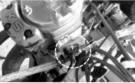
shown in Figure 5, the injection duration of the PFI injector were longer than the available time for two-stroke engine stratified charging at all operating conditions. Starting on about 8000 rpm at 100 % throttle opening, the injection durations were even longer than one cycle duration of two-stroke engine. Stratified charging mode could no longer be achieved using this injector. Placing this injector in direct contact with combustion chamber was also not an option since the injector will not be able to withstand the temperature and pressure. It was decided then to change injector position to the place shown in Figure 6 instead where the injector will be operated under homogeneous charging mode.
Figure 5. Simulated injection duration (including response time) of the gasoline injector at 100, 75, and 50 % throttle opening compared to the available time for two-stroke engine stratified charging and one cycle duration of two-stroke
engine
Because of its new position, the injector will always be protected by piston from the high pressure and temperature during compression and power stroke but will still be able to inject fuel directly to combustion chamber in period between the start of the scavenging port opening to the end of the scavenging port closing (120 CAD). This fuel injection arrangement is called low-pressure GDI which similar implementation with different engine geometry had been described in [2, 3] and [8].
5 The Injection Control System and the Injection Strategy
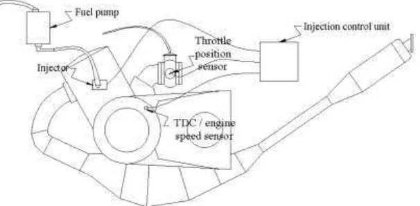
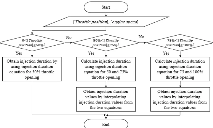
The configuration of the injection control system is presented in Figure 8. The injection control system used Autonics BF3RX fiber optic sensor as the Top Dead Center (TDC) position sensor and the engine speed sensor. A potentiometer attached to throttle cable were used as the throttle position sensor. All data from the sensors was sent to microcontroller PIC16F87XA for the calculation of the injection timing and injection duration. The Mass Air Flow (MAF) or Manifold Absolute Pressure (MAP) as well as temperature sensors were decided not to be incorporated in this injection control system due to the limitation in the microcontroller capability. This experimental injection system did not calculate injection duration based on the mass of the air flow ingested to the engine. The injection duration was calculated based on the fuel flow rate data in Figure 3 (a) that was later transformed to injection duration data at 100, 75, and 50 % throttle openings for the PFI injector presented in Figure 5.
Figure 7. The configuration of the injection control system
Figure 8. The method for calculating injection duration
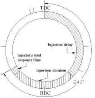
Figure 9 illustrates the method for injection delay calculation and injection execution procedure. Injection delay is defined as the length of time from TDC position signal to the start-of-injection signal. As can be seen in Figure 10, the injection was designed to be started after the end of injection delay and to be completed by the end of the scavenging port closing. At all conditions, the completions of injections are fixed but the start-of-injection will vary according to the variation of injection duration values. After the calculation of injection delay, the injection control system will check for the TDC signal. When the signal is obtained, the injection control system will perform the injection after the time calculated for the injection delay is ended.
7 Figure 10. The diagram showing relation between total available period, injection delay, injection duration and
injector’s total response time
The Performance of the Low-Pressure GDI
Fuel mass flow rate of the low-pressure GDI system being produced was measured and calculated in order to evaluate the compatibility of the injector and the overall performance of the fuel injection system. Figure 11 shows the fuel mass flow rate comparison between carburetor and low-pressure GDI fuel supply system. Fuel supply in injection control program was previously designed to deliver 20 to 30 % less than the carburetor fuel rate but the measurement results showed that this intended fuel supply characteristics can only be obtained at low engine speed and
small throttle opening. At condition other than that, low-pressure GDI’s fuel mass flow rate is
higher than the carburetor’s.
Figure 11. Fuel mass flow rate comparison between the time when the two-stroke engine used carburetor and the time when it used low-pressure GDI
CONCLUSION
A low-pressure GDI system which used PFI components and a generic / multipurpose microcontroller had been obtained in this work. The injection control system of the low-pressure GDI system used throttle position and engine speed data to determine the injection duration and
the start of injection. The injection system’s fuel supply characteristics was design to imitate the
fuel supply characteristics of the engine’s carburetor that was previously measured by varying
system was able to perform well at small throttle opening and low engine speed but it needed more improvement to operate better at other operating conditions.
REFERENCES
[1] Aziz A.A., Latiff Z.A., Ali M.F.M., Said M.F.M, Said M., Retrofitting Of Auxiliary
Components To Enhance The Performance Of A Single-Cylinder, Air-Cooled Gasoline Two-Stroke Engine, Jurnal Mekanikal, 2006
[2] Blair, G.P., Hill, B.W., Miller, A.J., Reduction of Fuel Consumption of a Spark-Ignition
Two-Stroke Cycle Engine, SAE, 1983
[3] Douglas, R., dan G.P. Blair, Trans SAE Paper No. 820952,91, SAE, 1982
[4] Hooper, P.R., Al-Shemmeri, T., Goodwin, M.J., Advanced Modern Low Emmision
Two-Stroke Cycle Engine, Proceedings of the Institution of Mechanical Engineers, Part D: Journal of Automobile Engineering, 2011
[5] Houston R., Cathcart G., Combustion and Emissions Characteristics of Orbital's Combustion
Process Applied to Multi-Cylinder Automotive Direct Injected 4-Stroke Engines, SAE Paper 980153, 1998
[6] Leighton, S., M. Cabis, dan M. Shouthern, Trans SAE Paper No.94187,91, SAE, 1988
[7] Takagi, Y, A New Era in Spark-Ignition Engines Featuring High-Pressure Direct Injection,
Twenty-Seventh Symposium on Combustion, Combustion Institute, 1998
[8] Winkler, F., dan Kirchberger, R., Low Pressure Fuel Injection Strategies for Low Emission
Two-Stroke Scooter Engine, IEA AMF Annex XXXIII, 2008
[9] Zhao F., Lai M. C., Harrington D. L., Automotive Spark-Ignited Direct-Injection Gasoline