DEVELOPMENT OF A CURRENT CONTROL
ULTRACAPACITOR CHARGER BASED ON DIGITAL
SIGNAL PROCESSING
Ahmad Saudi Samosir
Department of Electrical Engineering, Universitas Lampung Jl. Sumantri Brojonegoro No.1, Bandar Lampung
Email: [email protected]
Abstrak
Kapasitor-ultra selalu digunakan sebagai penyimpanan energi listrik jangka pendek karena memiliki beberapa keunggulan, seperti kerapatan daya yang tinggi (5kW/kg), siklus hidup yang panjang dan efisiensi pengisian/pembuangan muatan yang sangat baik. Tidak seperti baterai, kapasitor-ultra dapat diisi dan dipakai pada rating arus yang sama. Hal ini sangat berguna dalam sistem pemulihan energi seperti pengereman dinamik pada sistem transportasi. Ini adalah beberapa karakteristik kapasitor-ultra yang harus diingat ketika mengintegrasikan/merancang sebuah sistem pengisian untuk aplikasi kapasitor-ultra. Sebuah kapasitor-ultra dengan muatan kosong atau tanpa muatan akan bersifat seperti rangkaian pendek bagi sumber catu daya. Kebanyakan catu daya biaya rendah melipatgandakan arus keluaran akibat hubungan arus pendek, membuat mereka tidak cocok untuk pengisian dari kapasitor-ultra. Kapasitor-ultra memiliki induktansi seri yang rendah sehingga mudah distabilkan dengan pengisi daya mode pensaklaran. Konstanta waktu RC dari rangkaian pengisian pasif biasanya terlalu panjang. Oleh karena itu, regulator linier tidak efisien untuk pengisian kapasitor-ultra. Pada makalah ini disajikan rancang bangun dari sebuah pengisi kapasitor-ultra dengan kendali arus berbasis Digital Signal Processing (DSP).
Kata kunci: DSP, kapasitor-ultra, pengendali arus, pengisi kapasitor-ultra
Abstract
Ultracapacitor usually use as a short-term duration electrical energy storage because it has several advantages, like high power density (5kW/kg), long lifecycle and very good charge/discharge efficiency. Unlike batteries, ultracapacitors may be charged and discharged at similar rates. This is very useful in energy recovery systems such as dynamic braking of transport systems. Here are a few characteristics of ultracapacitors that should be kept in mind when integrating/designing a charging system for the intended application. An ultracapacitor with zero charge looks like a short circuit to the charging source. Most of low cost power supplies fold back the output current in response to a perceived short circuit, making them unsuitable for charging of ultracapacitors. Ultracapacitors have a low series inductance allowing easy stabilizing with switch mode chargers. The RC time constant of passive charging networks is usually too long. Therefore, linear regulators are inefficient components for ultracapacitor charging. In this paper, the development of a current control ultracapacitor charger based on Digital Signal Processing (DSP) is presented.
Keyword: current control, DSP, ultracapacitor, ultracapacitor charger
1. INTRODUCTION
TELKOMNIKA Vol. 7, No. 3, Desember 2009 : 145 - 150
Ultra-capacitors, also known as supercapacitors or Electric Double Layer Capacitors (EDLCs), store energy by accumulating charges on positive and negative electrodes separated by an insulating dielectric. The stored voltage is limited by the voltage-withstand-strength of the dielectric. Similar to battery, an ultra-capacitor could be stacked to produce modules with higher voltage or currents. Because of electrostatic nature of capacitor rather than chemical reaction as batteries, the ultra-capacitor has the merits of rapid charge and discharge, longer life cycle, easy maintenance, low environmental impact compared with battery storage [2]. Due to capacitance of several hundred farads and high power density, the ultracapacitor presents more advantages then a battery or an electrostatic capacitor [3].
In terms of energy and power density, ultra capacitors can therefore be placed between batteries and conventional capacitors [4-5]. An ultra-capacitor is an electrochemical component which mimics characteristics of very high value capacitors. As a capacitive element, the ultracapacitor has no charge/discharge memory effects allowing charging and discharging hundreds of thousands of cycles without any effect on the storage capacity. Also with its very low equivalent series resistance (ESR), these components can be charged and discharged at rates far greater than the best of battery technologies.
There are a few characteristics of ultracapacitors that should be kept in mind when integrating/designing a charging system for the intended application. An ultracapacitor with zero charge looks like a short circuit to the charging source. Standard battery charging systems usually do not operate well with ultra-capacitors because these components appear as a virtual short circuit to the charging system [6-11]. So, standard battery charging systems are unsuitable for charging of ultracapacitors. In this paper, an ultracapacitor charger with current mode control is designed. This charger controller is implemented by TMS320F2812 eZdsp board.
2. ULTRACAPACITOR CHARGER DESIGN
Charging of ultracapacitors is simple while at the same time may present some unique challenges. Unlike batteries, ultracapacitors may be charged and discharged at similar rates. This is very useful in energy recovery systems such as dynamic braking of transport systems.
An Ultracapacitor charger is a device used to put energy into an Ultracapacitor by forcing an electric current through it. The charge current depends upon the technology and capacity of the Ultracapacitor being charged.
2.1. Constant Current Charging
A DC-to-DC constant current regulator is the simplest form of active charging. Either a buck or boost regulator may be used depending on the application. A buck regulator is the preferred topology due to the continuous output charge current. The power losses or ultracapacitor heating is proportional to current squared times the duty cycle [7, 11].
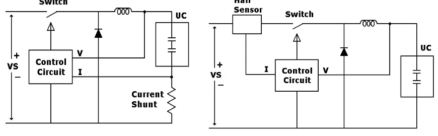
A simple constant current charger may be built with standard power supply IC’s. The current limit would be set to the required charge current and the voltage limit would be set to the maximum required voltage. An example circuit layout is provided in Figure 1.
Figure 1. Constant Current Charging
2.2. Constant Power Charging
When charge time is critical, constant power charging provides the fastest charge method. Constant power charging can transfer all the available power from the charge source into the energy storage capacitors. Drawing a constant current from the source at a constant voltage is a simple implementation of constant power charging. This usually requires that a maximum switching current of 2.5 times the nominal be established to prevent overloading the switching circuitry when the ultracapacitor voltage is below 40% of maximum. An example schematic is provided in Figure 2.
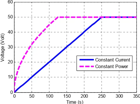
To quantify the significance of constant power charging the following example is provided and illustrated in Figure 3. A 100 farad, 50V module is charged from a 50V, 20 amp power supplies. In the constant current waveform the module is charged at the maximum power supply current of 20 amps. In the constant power waveform the module is charged at a constant 1000 watts. The maximum charge current from the constant power charger was set at 50 amps.
Figure 3. Constant Current vs. Constant Power Charging Time
The constant 20 amp charge current required 250 seconds to charge the module to 50 volts. The 1000 watt constant power charger required 145 seconds to charge the module to 50 volts. For the constant power waveform 50 amps charging current was utilized until the ultracapacitor module voltage reached 20 V with this limit is set by the switching circuitry. Constant power charging is very useful in dynamic braking systems. This allows a constant power to be extracted from the vehicle’s momentum and transferred to stored electrical energy. 2.3. The Proposes Ultracapacitor Charger
In this paper, a DSP based current control ultracapacitor charger is design and implemented. This charger is using a buck regulator topology in power circuit. Due to an ultracapacitor with zero charge looks like a short circuit, so, current mode control is chose as the control strategy.
Current mode control as usually implemented in switching power supplies actually senses and controls peak inductor current. Current mode control is a two-loop system as shown in Fig. 4. The switching power supply inductor is “hidden” within the inner current control loop. This simplifies the design of the outer voltage control loop and improves power supply performance in many ways, including better dynamics. The objective of this inner loop is to control the state-space averaged inductor current, but in practice the instantaneous peak inductor current is the basis for control. If the inductors ripple current is small, peak inductor current control is nearly equivalent to average inductor current control.
TELKOMNIKA Vol. 7, No. 3, Desember 2009 : 145 - 150
Figure 4. DSP based Current Mode Control ultracapacitor charger
3. RESULTS AND ANALYSIS 3.1. Simulation
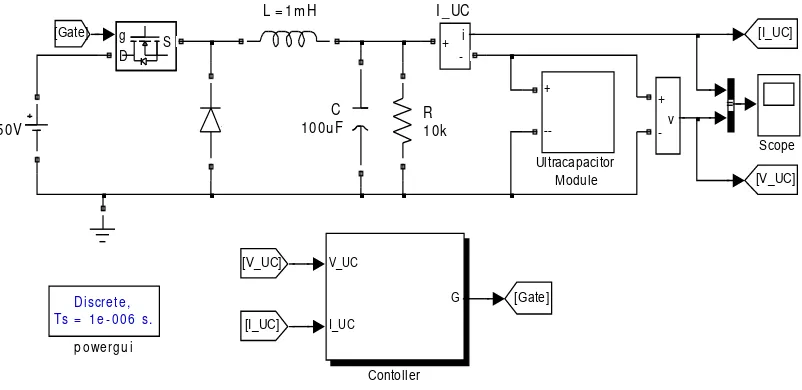
A comprehensive simulation analysis was conducted to verify the ultracapacitor charger performance. The performance of ultracapacitor charger is tested through simulation by using MATLAB SIMULINK. The ultracapacitor charger scheme and the controller are modeled in Simulink as shown in Figure 5.
Discre t e ,
Figure 5. The ultracapacitor charger scheme simulation model
Table 1. Simulation model parameters
Parameter Value
Input Voltage 50V
Reference Current 10, 20,30, 40, 50, 100A
Inductance L 1mH
Capacitance C 400uF
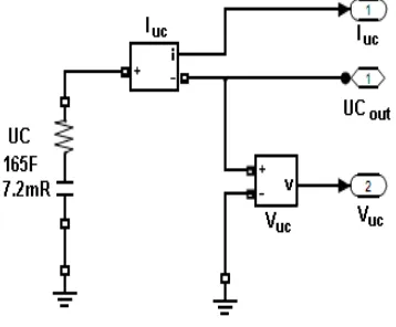
The model parameters of ultracapacitor are listed in Table 1. The model of ultracapacitor module block is shown in Figure 6. The control goal is to regulate output current Io=10A up to 100A. The simulation results for charging of BMOD0165 Ultracapacitor are shown in Figure 7.
Figure 6. Ultracapacitor module block
Figure 7. Charging of BMOD0165 ultracapacitor simulation result
3.2. Experiment
Validation of simulation result is investigated by experimentation. To show the performance of the proposed ultracapacitor charger, a prototype of an ultracapacitor charger is developed. For flexible and rapid prototyping design approach, a TMS320F2812 eZdsp board is used. The TMS320F2812 eZdsp board is employed to implement the current control and the PWM signal generator. Figure 8 shows the complete hardware set-up for ultracapacitor charger implementation, while Figure 9 shows the TMS320F2812 eZdsp board that has been employed in this work.
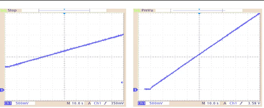
Figure 10 and 11 show the experiment results of the ultracapacitor charger performance. Ultracapacitor voltage waveform with 5 A charging current is shown in Figure 10 and waveform with 10 A charging current is shown in Figure 11. Ultra capacitor current is constant when the voltage of ultracapacitor is increase.
Figure 8. Complete hardware prototype for implementation
TELKOMNIKA Vol. 7, No. 3, Desember 2009 : 145 - 150 Figure 13. Ultracapacitor voltage waveform
with 5 A charging current
Figure 14. Ultracapacitor voltage waveform with 10 A charging current
4. CONCLUSION
This paper presents an implementation of current control for ultracapacitor charger. The performance of ultracapacitor charger has been tested. From the simulation and experiment results, the proposed ultracapacitor charger can generate a constant charging current to charge the ultracapacitor.
REFERENCES
[1]. Giesselmann, M.; Heeren, T.; Helle, T., “Compact, high power capacitor charger”, Pulsed Power Conference, pp.707-710, June 2006.
[2]. Min Chen; Rincon-Mora, G.A., “Accurate, Compact, and Power-Efficient Li-Ion Battery Charger Circuit”, IEEE Transactions on Circuits and Systems, pp. 1180 – 1184, Nov 2006.
[3]. Thimmesch, David, “An SCR Inverter with an Integral Battery Charger for Electric Vehicles”, IEEE Transactions on Industry Applications, pp. 1023-1029, July 1985.
[4]. Berisha, S.H.; Karady, G.G.; Ahmad, R.; Hobbs, R.; Karner, D.; “Current harmonics generated by electric vehicle battery chargers”, Power Electronics, Drives and Energy System for Industrial Growth Conference, pp. 584-589, Jan 1996.
[5]. Mersman, C.R.; Dillman, N.G.; Morcos, M.M.; “A novel microprocessor-based Ferro-resonant battery charger for electric vehicles”, Electrical and Computer Engineering Conference, pp. 327 – 330, May 1996.
[6]. Chuang, Y.C.; Ke, Y.L, “High efficiency battery charger with a buck zero-current-switching pulse-width-modulated converter”, IET Power Electronics Journal, pp. 433-444, December 2008.
[7]. Pellegrino, G.; Armando, E.; Guglielmi, P., “Integrated battery charger for electric scooter”, European Conference on Power Electronics and Applications, pp. 1-7, Sept. 2009.
[8]. Wu-Shun Jwo; Wei-Liang Chien, “Design and Implementation of a Charge Equalization Using Positive/Negative Pulse Charger”, Industry Applications Conference, pp. 1076-1081, Sept. 2007.
[9]. Liang-Rui Chen; Jin-Jia Chen; Neng-Yi Chu; Gia-Yo Han, “Current-Pumped Battery Charger”, IEEE Transactions on Industrial Electronics, pp. 2482-2488 , June 2008.
[10]. Chia-Hsiang Lin; Chi-Lin Chen; Yu-Huei Lee; Shih-Jung Wang; Chun-Yu Hsieh; Hong-Wei Huang; Ke-Horng Chen, “Fast charging technique for Li-Ion battery charger”, Electronics, Circuits and Systems Conference, pp. 618-621 , Sept. 2008.