RELIABILITY ANALYSIS BASED ON IMPLEMENTATION OF LOOP
RESTORATION SCHEME AND PROPOSED ADDITIONAL PICK
-
UP
CURRENT SENSOR IN DISTRIBUTION NETWORK
PUBLIKASI ILMIAH
Proposed as one of the requirements to complete the degree of Bachelor of Engineering
At the Department of Electrical Engineering, Faculty Engineering
Universitas Muhammadiyah Surakarta
By:
M. ANNAS ALBAB FAUZI
D 400 122 004
DEPARTMENT OF ELECTRICAL ENGINEERING
ENGINEERING FACULTY
UNIVERSITAS MUHAMMADIYAH SURAKARTA
HALAMAN PERSETUJUAN
RELIABILITY ANALYSIS BASED ON IMPLEMENTATION OF LOOP
RESTORATION SCHEME AND PROPOSED ADDITIONAL PICK
-
UP
CURRENT SENSOR IN DISTRIBUTION NETWORK
SCIENCE PUBLICATION
By:
M. ANNAS ALBAB FAUZI
D 400 122 004
Has been checked and approved by:
Supervisor
HALAMAN PENGESAHAN
RELIABILITY ANALYSIS BASED ON IMPLEMENTATION OF LOOP
RESTORATION SCHEME AND PROPOSED ADDITIONAL PICK
-
UP
CURRENT SENSOR IN DISTRIBUTION NETWORK
OLEH
M. ANNAS ALBAB FAUZI D 400 122 004
Telah dipertahankan di depan Dewan Penguji Fakultas Teknik
Universitas Muhammadiyah Surakarta Pada hari Rabu, 18 Mei 2016 dan dinyatakan telah memenuhi syarat
Dewan Penguji:
1.Ir. Jatmiko, M.T. (……..……..)
(Ketua Dewan Penguji)
2.Agus Supardi, S.T. M.T. (………)
(Anggota I Dewan Penguji)
3.Aris Budiman, S.T. M.T. (……….)
(Anggota II Dewan Penguji)
Dekan,
PERNYATAAN
Dengan ini saya menyatakan bahwa dalam naskah publikasi ini tidak terdapat karya yang
pernah diajukan untuk memperoleh gelar kesarjanaan di suatu perguruan tinggi dan sepanjang
pengetahuan saya juga tidak terdapat karya atau pendapat yang pernah ditulis atau diterbitkan orang
lain, kecuali secara tertulis diacu dalam naskah dan disebutkan dalam daftar pustaka.
Apabila kelak terbukti ada ketidakbenaran dalam pernyataan saya di atas, maka akan saya
pertanggungjawabkan sepenuhnya.
.
Surakarta, 18 Mei 2016 Penulis
RELIABILITY ANALYSIS BASED ON IMPLEMENTATION OF LOOP RESTORATION SCHEME AND PROPOSED ADDITIONAL PICK-UP CURRENT SENSOR IN
DISTRIBUTION NETWORK
Abstrak
Sistem distribusi mengambil tanggung jawab dalam penyediaan tenaga listrik kepada pelanggan. Ini berarti kepuasan pelanggan memainkan peran utama dan menjadi bagian penting untuk perusahaan listrik. Oleh karena itu, peningkatan kualitas sistem distribusi adalah suatu keharusan. Penerapan distribution feeder automation system (DFAS) melalui sistem SCADA menjadi solusi terbaik untuk masalah kepuasan pelanggan. Hal ini dapat mengakibatkan peningkatan kehandalan, kualitas yang konsisten dan layanan teknologi tinggi. Loop restoration strategy (LRS) adalah metode DFAS khusus di tingkat penyulang yang digunakan oleh utilitas listrik untuk meningkatkan distribusi keandalan sistem. The LRS dikendalikan dan dikelola oleh automatic control system (ACS). Dengan demikian, tulisan ini mencoba untuk mengusulkan mekanisme ACS sebagai prosedur otomatisasi SCADA. Selanjutnya, mengoptimalkan prosedur otomatisasi dalam makalah ini akan menyajikan memanfaatkan dan menggabungkan pick-up status alarm saat ini dengan jenis lain dari sensor alarm yang sudah digunakan di stasiun SCADA induk. Pelaksanaan pick-up status alarm saat akan memberikan keuntungan karena para perbaikan otomatis dan otomatisasi kinerja. Sebuah langkah demi mengevaluasi langkah prosedur diusulkan dalam makalah ini menilai dampak dari LRS dan kombinasi LRS dan SCADA sebagai mekanisme otomatisasi sistem distribusi dan analisis status alarm saat pick-up dalam sistem SCADA.
Kata kunci:otomasi,arus pick-up,keandalan.
Abstract
Distribution system take the responsibility in electricity supply to customer. It mean the customer satisfication plays the main role and become the important part to electricity company. Therefore, the enhancement of the quality of distribution system is a must. Implementation of distribution feeder automation system (DFAS) through SCADA system become the best solution to customer satisfaction problems. It can result the improvement of reliability, consistent quality and high-tech services. Loop restoration strategy (LRS) is a special DFAS method in the feeder level which is used by electric utilities to improve distribution system reliability. The LRS is controlled and managed by its automatic control system (ACS). Thus, this paper try to proposed the ACS mechanism as the SCADA automation procedure. Furthermore, optimizing automation procedure in this paper is going to present the utilize and combining the pick-up current alarm status with another type of alarm sensor that already used in SCADA master station. The implementation of pick-up current alarm status will give advantages due the autorecovery and automation performance. A step by step evaluating procedure is proposed in this paper asses the impact of the LRS and the combination of LRS and SCADA as the automation mechanism of distribution system and the analysis of the pick-up current alarm status in SCADA system.
INTRODUCTION 1.
Electricity has become the most important commodity in human being life nowadays. Therefore, Power companies must continually improve the reliability of power supply and maintain the customer satisfaction through the enhancement of service quality. PLN, as the state electricity company in Indonesia, takes the responsibility to maintain and improve the quality of electricity distribution to customers. To these ends, PLN should focus on the distribution feeder automation system (DFAS). The DFAS integrates computers, communications, and control technology into distribution system. It is composed of control center facilities, feeder remote terminal units (FRTUs), feeder terminal units (FTUs), overhead or underground automatic line switches, over current relays (OCR), ground fault relays (GFR), and communication systems. The combination of automatic line switches, over current relays (OCR), ground fault relays (GFR) are being installed in DFAS to
replace the traditional ones.
Increasing the reliability of distribution network, it is desirable to use the most reliable distribution network type which is can develop from the current distribution network. Due to this, the level reliability shows the adequate electrical supply to its customers as economally as possible. With growing demand and increasing dependance on electricity supplies, the necessity to achive an aceptable level of reliability, quality and safety at an economic price, the utility have to evolve and improve the system continously depending upon the requirementof the customers. However, nowadays the most distribution network which is used by PLN is radial distribution network which is not fairly good to perform as distribution feeder automation system. Thus, an approach is proposed in this paper to enhance the radial distribution network to spindle type of distribution network due to the improvement of reliability and also minimizing the improvement budget.
The spindle distribution network, one of primary distribution system, is the combination of the radial system which is the edges in each feeder is connected in substation feeder circuit and has express feeder in the centre of network. Express feeder must be in a state of continous voltage and has function to guarantee the operation of distribution system to distribute electrical energy when the system is maintained or when the fault occurs in system.
To meet the increasing demands of network reliability, particularly in the speed of recovery and minimize the impact of disruption disorders (disorders area localization). It should coordinate the spindle distribution system with the implementation of Loop restoration Scheme (LRS) and SCADA
motorized, Relays as sensor detector to give pick-up current alarm status and RTU which is connected to master stations. This coordination is expected to increase the quality and reliability of the distribution network because the distribution network condition can be monitored in real time and in case of disruption can be known on which areas can be detected and isolating. Therefore, the
supply of electricity can continually distributed to customers and effectively improving the power quality and reduce the SAIFI (System Average Interruption Frequency Index), SAIDI (System Average Interruption Duration Index) and CAIDI (Customer Average Interruption Duration Index).
An approach is proposed in this paper to quantitatively assess the comparison of native circuit and proposed circuit reliability index and the impacts of the reconfiguration of 20 kV distribution network which can perform auto recovery process integrated with loop restoration scheme through fiber optic connection among the equipment to trigger the switching procedure that controlled by SCADA system. The proposed technique is prospected to minimize the SAIDI (System Average Interruption Duration Index) and CAIDI (Customer Average Interruption Duration Index), Improving the continuity of electricity service and directly isolate the fault location from main system.
RESEARCH METHOD 2.
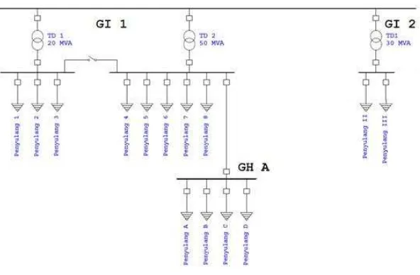
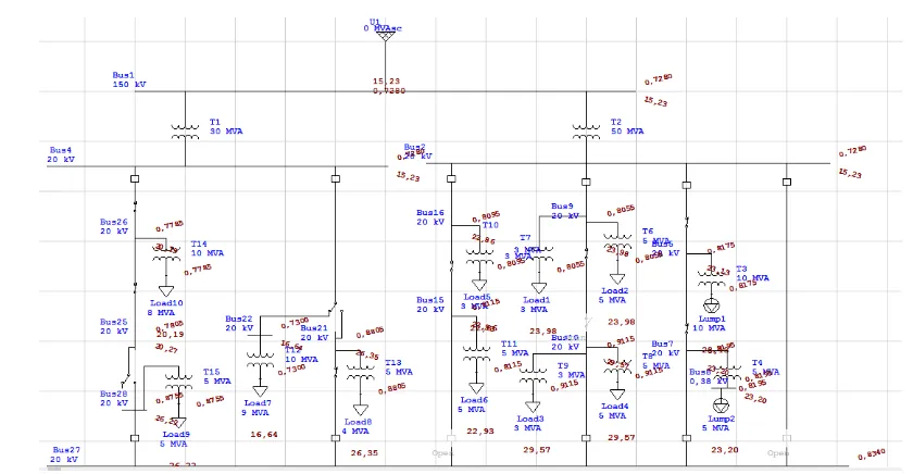
Figure 1. Single line diagram of the current 20kV distribution circuit
An approach in this research is using the ETAP 12.6 to analyze and evaluate the reliability index both of the current 20 kV distribution circuit in Padang, West Sumatra (that shows in the Fig. 1 and Fig. 2) and the propoesed circuit. Moreover, this research also propose and do analysis about the implementation of SCADA with novel setting of pick-up current alarm status. The current circuit is using radial distribution circuit. The approach and development in this paper is only to analyze and
evaluate 5 feeders and there are devided into two group, group 1 consist of Sudirman feeder and BRI feeder; group 2 consist of Metro feeder, Wahidin feeder and Cokro feeder. Furthermore, one of the
Figure 2. Native circuit
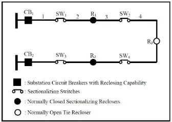
The automation mechanism in this paper is using the function of SCADA and the circuit reconfiguration through the LRS which is tipically utilizes a predetermined number of reclosers installed in series between two distribution feeders. This system consist of some switching device to operate the automation system. First, in each distribution feeders was installed by the circuit breaker with auto-reclosing(motorized) capability that has purpose on protection system. Then, a normally closed sectionalizing recloser is also installed on each feeder and the last it is typically applied to two feeders by installing a normally open tie recloser at a tie point between two feeders, as shown in Fig.3.
Figure 3. Typical Configuration of Loop Restoration Strategy
The automation switching provides isolation of any faulted sector within the distribution feeder while simultaneously reestablishing service to all customers unaffected by the faulted sector within a relatively short period of time. This procedure is controlled and managed by a special automatic control system (ACS). In this paper is going to compare between proposed system without LRS system and proposed system with LRS are considered in analysis. Basically the approach in this paper is using the automation through SCADA by switching command function among the protection device which is equipped with OCR and GFR as the sensor to detect the fault on the feeder and the communication in this SCADA system is using fiber optic lines.
Through the combination between the LRS and the reconfiguration the radial into spindle system, this paper bring the novel approach of DFAS (Distribution Automation Feeder System) thruogh the function of SCADA. This configuration will be installed with additional circuit breaker in each feeder and the express feeder is also going to installed in the system in order to keep the electricity when faults occur. The fault is detected by the relay as the sensor, ground fault relay (GFR) and Over current relay (OCR) is used to cover all fault condition. Fig.4 until Fig.7 shows the working principle of the system when the outaage occurs. Fig.4 shows the normal operation of the system which is the express feeder always in electrify condition and one of the Circuit Breaker in the
relay sensor sends an alarm status to the master station thus in the feeders and the system can automatically detect the fault and directly make both of circuit breaker in the feeder become open condition. Fig.6 shows the Load break switch which enclose on either side is automatically in open condition because the measurement equipment sends signal to Master station and Master Station
sends trip order to LBS to do the switching procedure. Finally the Fig.7 shows the backup plan when the areas whis is lossing the electricity supply get their new supply from the express feeder after the circuit breaker in the end point of each feeder do the switching procedure become closed condition.
Figure. 4 Proposed system in normal condition and Figure. 5 Proposed system when fault occur in feeder
Figure. 6 Proposed system runs isolation scenario and Figure. 7 The fault point was isolated
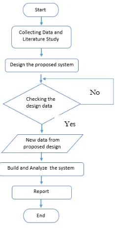
Generally, The research can be constructed into the bellow flowchart :
Figure 8. Research Flowchart No
RESULT AND ANALYSIS 3.
A modular approach above is used to evaluate the reliability and develop the system and its reliability through the implementation the LRS and reconfiguration of the network circuit. Then, this part is conducting the comparison of simulation result. Furthermore, the foremost aim of this study is to see how reliability could be improved in the distribution system by reconfigurate the model of network and the implementation of LRS and switching interlock enforcer thruogh ETAP software. After conducting the comparison between both of reliability of the system, in this paper is going to presented the novel setting in SCADA through the additional setting of pick-up current alarm status in master station.
3.1 Reliability Index Calculation by Using Loop Restoration Scheme Method
In this chapter is going to comparing the reliability index of implemented system in the field by PLN and the implementation of proposed system which is using loop restoration scheme through the simulation function in ETAP 12.6.
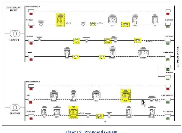
The quality of the existing system and the application of the proposed technique to a multi-load point distribution system is illustrated from distribution reliability test system result. Furthermore, the proposed system which is done by reconfiguring the system by implementing of loop restoration
scheme and switching interlock enforcer function in ETAP 12.6 can be seen in Fig.9.
Figure 9. Proposed system
the 150kV/20kV subbstation, fuses, circuit breaker, reclosers and switches are ignored, The circuit breakers and reclosers are assumed to open and isolate a fault and it is assumed that substation circuit breakers have reclosing capability by connecting circuit breaker to overcurrents relays or ground fault relays as the input data. Also, when employing the LRS for the proposed system, the
intermediated section switches are replaced by normally closed sectionalizing and open tie reclosers. Respectively, the 5 feeder has devided into 2 groups which are interconnected to each other through a normally open tie recloser and it is considered as a loop restoration scheme with express feeder additional to develop smart spindle. Fig. 9 shows the proposed system after implementing the recloser loop schemes and intelligent loop restoration system.
In order to quantitatively examine the impacts of two introduced of loop restoration scheme on distribution system reliability, several comparative studies are conducted. An overall brief description of various case studies is as follows:
Case 1 : The LRS is not implemented
Case 2 : The LRS implementation on the system.
Case 3 : The switching interlock enforcer implementation on LRS which is equipped with express feeder.
The comparison between native in fig.10 and proposed system in fig.11 is presented in table 1.
Figure.11 Reliability analysis of proposed circuit
Proposed system 0,7859 16,9828 21,609 0,9981 0,00194
C
Existing System 1154,283 0,00 96,1902 0,00
Proposed system 980,661 0,00 81,7218 0,00
Based on data from table, it is consist of two different simulation result that had been conducted. The table shows the enhancement of reliability index from proposed system compared to existing system. First, to develop the proposed system we should consider the condition of system. There are following explanation of the scenario that are implemented on the system. (1)First scenario is separting the existing system on Simpang Haru susbtation into two part using loop restoration scheme method by adding two normally open tie circuit breaker.(2)Second scenario implemented by replacing some LBS and swtich with LBS motorized or recloser.(3)Implementing the switching interlock enforcer on proposed system.
Installed with the normally open tie circuit as the connector or backup system and adding the express feeder imam bonjol 1 and express feeder imam bonjol 2 on both of system as the requirement to develop the radial dsitribution to spindle distribution system due to the enhancement of the reliability index of distribution system.
Figure 10. Proposed system
Installing the LBS motorized or recloser in each feeder to implement the Loop restoration Scheme.
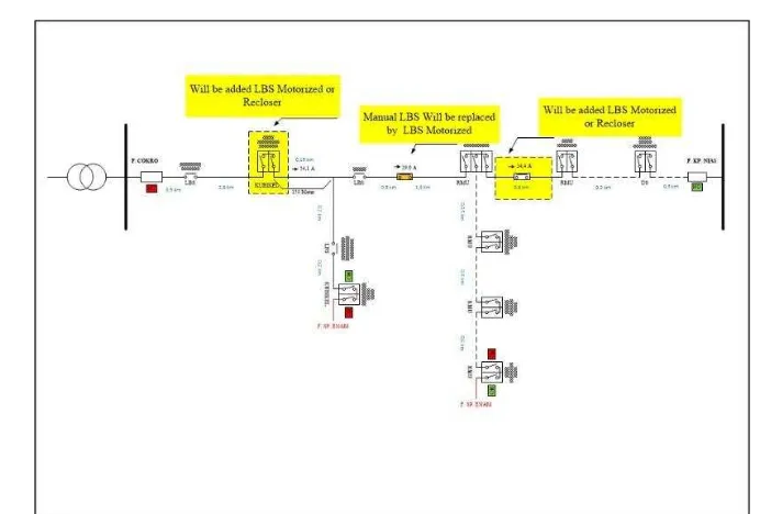
a. To implementation of the loop restoration scheme is done by adding the LBS motorized or recloser in each feeder and the first scenario is to install three LBS motorized or recloser in Cokro feeder – KP Nias Feeder
b. The second alteration is installing the new LBS motorized or recloser and replace the manual LBS with LBS motorized or recloser in Wahyudin feeder to SP Enam feeder.
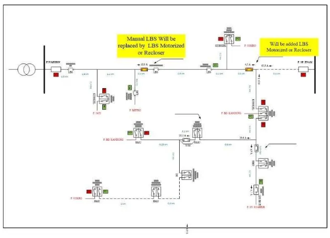
Figure 12. Wahidin feeder-SP Enam feeder as feeder 2
c. The third alteration is installing two LBS motorized or recloser in Metro feeder to Permindo feeder.
Figure 13. Metro feeder-Permindo feeder as feeder 3
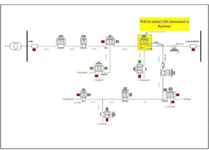
Figure 14. BRI feeder-BD Kandung feeder as feeder 4
e. The last alteration is replace the manual LBS with LBS motorized or recloser and install new LBS motorized.
Figure 15. Sudirman feeder-Ramayana feeder as feeder 5
Implementation of switching interlock enforcer, this system uses the interlock logics entered in the AC switching device to implement interlock schemes which need to be implemented during special system operating conditions including maintenance and outage modes.
feeder as feeder 3; and Imam Bonjol express feeder 1) and system 2 ( BRI feeder-BD Kandung feeder as feeder 4 ;Sudirman feeder-Ramayana feeder as feeder 5; and Imam Bonjol express feeder 2) influence the differences of reliability index of the both system which is distinguished by the amount
of the feeder. System 1 is constructed by combining three feeders with additional one express fedeer and system 2 is constructed by combining two feeders and one express feeder. However both of system shows different value but the installation of new sectional switch improving the reliability index on the system.
3.2 Reliability Index Comparison
The result presented in the Figure.456 which is shows the comparison between the reliability index of normal system and the proposed system after conducting the simulation in ETAP.
The data from the table shows the enhancement of the reliability index in each feeder which
was originally only installed by Circuit Breaker and Load Break Swtich, however, the installation of Sectional Switch and Recloser in each feeder and the replacement of Manual Load Break Switch with Motorized Load Break Switch. Thus, the Load Restoration Scheme seen to be effective in its application of the system.
Table 3. The relibility index comparison of each feeder
Case 2
) Feeder (f/cost.year) SAIFI (h/cost.year) SAIDI (h/cost.interruption) CAIDI
Feeder 1 0,7550 12,4180 16,448
Feeder 2 0,8055 17,2380 21,400
Feeder 3 0,7485 12,0930 16,156
Feeder 4 0,7485 12,0930 16,156
Feeder 5 0,7485 12,0450 16,092
3.3 SCADA setting with Pick-up Alarm Status in Master Station
In this chapter is giong to present the proposed SCADA system on distribution circuit. The working principle is done by designing the automation system and do the ntwork mapping procedure and utilize the fault current sensor on each LBS thus the zones of source interruption or fault that occurs can be known.
Sensors are used to detect the disorder is pick-up alarm status which has already installed on each LBS. Pick-up status has been selected for the event of large and small disturbance on the network. Relays on each LBS can immediately give an alarm signal to master station before the
circuit breaker in substation trip. So that any disturbance will always be monitored in accordance zone or source of the disturbance before the flow of fault current is disconnected by relays protection
at the base. The kind of relays logic in LBS can be seen in the following figure :
Figure 16. Input setting on SCADA Master Station
GFR and GFR instan. Te setting combination of six types of alarm status can accommodate all the possibilities that exist in the field. Thus the algorithm of the system can be seen in fig.17.
Figure 17. SCADA Algorithm
The common logic setting used without including the pick-up current status. Thus, when the interruption occurc in circuit it will lead the relays in substation trip first before the LBS relays work and causing the source of interference can not be detected by LBS. Therefore, the implementation of pick-up current setting is included as the alarm references when the fault occurs so that all fault conditions can be known by LBS as well as SCADA system at the master station. The equipment that responsible as the receiver and transmitter of the data input
Figure 17. RTU Location
Figure 18. RTU and RMU Installation
When the fault occurs, SCADA system will perform pooling to each device on the distrupted networks. If there is equipment that does not provide feedback that the operating mode will automatically be terminated. Likewise, if at the time of LBS can not provide feedback status of its open-close condition thus the automatic operation will be terminated by the SCADA recovery, on the equipment installed must qualify taht switching equipment has been equipped with motorized switch and able to detect currents disorders, voltage and power factor.
The implementation of this automation system has the main purpose such as (1) Reducing the normalization duration from the normal condition on existing system because after the implementation of the automation system the duration of the network become faster due the speed of LBS switching duration about 15 second. Thus the expected time to perform auto recovery is based on switchin duration of LBS motorized. (2) Reducing the outages area (3) Optimize the switching equipment life (4) Enhance the service to custommers.
3.4 Automation Procedure
This chapter is going to analyze the automation of isolation procedure when the fault occurs in feeders area. In order to perform the automation. The auto -recovery system from SCADA system will perform when the fault occurs on the feeders, there are some analysis and the working principle of the SCADA system.
Figure 20. Fault Occurs in Sudirman feeder-Ramayana feeder
has already equipped with RTU work as the sensor to detect and send the pick-up alarm status to master station. Thus the master station will perform isolation procedure, first, the master station will send Open switching command to CB near substation. Second the fault current which was detected by both of LBS Ratulangi and LBS Belakang Olo will make them in open
position. Finally the CB that connected to express feeder and CB near substation will get closed switching command from master station. Thus the fault point was isolated and the blackout area get electricity from express feeder.
Figure 19. Fault Occurs in Cokro Feeder-KP Nias Feeder
Fig.19 shows the fault that occurs in cokro feeder-KP Nias feeder then the system will perform auto-recovery. The pictures shows the fault that occurs between LBS Ranah and LBS AR.Hakim. Then the fault is detected by both of OCR and GFR relays as the protection equipment and the kind of fault is divided into 6 categories. Then the RMU which has already equipped with RTU work as the sensor to detect and send the pick-up alarm status to master station. Thus the master station will perform isolation procedure, first, the master station will send Open switching command to CB near substation. Second the fault current which was detected by both of LBS Ranah and LBS AR.Hakim will make them in open position. Finally the CB that connected to express feeder and CB near substation will get closed switching command from master station. Thus the fault point was isolated and the blackout area get electricity from express feeder.
With the implementation of distribution automation system then obtained financial benefits in the form of accelerated normalization of disturbance and outages regional risk reduction that will lead to reduced risk of losing KWh. Based on the data obtained disorders
following data :
Table. 4 Financial Study
Fault SCADA automation because the SCADA system is going to aceelerating the interference duration and completing the isolation process.
CONCLUSION 4.
Based on final project in design and implementation of proposed distribution automation system through assesment of the impact the loop restoration scheme on the distribution system reliability indices. In order to demonstrate the proposed technique, comparative studies was conducted using a typically distribution reliability test system.
The result presented indicate the benefit of employing the LRS for automating distribution feeder. The evidence is presented in the following point : (1) Reliability index of the existing system based on ETAP simulation resulting some value SAIFI 0,8297; SAIDI 20,1339; CAIDI 24,266.
pick-up current sensor and split feeder into zones, the search of disorder location becomes easier and more certain that avoid doing trial and error for the normalization of feeders. (5) Switching equipment should be equipped with motorized switch and able to detect currents disorders, voltage and power factor.
Finally, this final project report has been fulfilled as expected. For the future, hopefully there
is a development of these system and can be implemented in existing system.
ACKNOLEDGEMENT
All praise and thanks to Allah, God of the worlds, above all grace so that this final project report
with title “Reconfiguration of Radial Distribution Network by Evaluate the Reability Index and
Implementation of Loop Restoration Scheme to Develop Smart Spindle Distribution Network” had been finished and approved. This project report attempts to bring under one cover the entire hard
work and dedication put in by me in the completion of the project work in reconfiguration and reliability analysis of distribution network.
I would like to acknowledge the invaluable guidance and concern of my advisor, Ir. Jatmiko M.T. Throughout this writing and research process, he always accepted my ideas with an open mind and gave me the maximum opportunity to contribute to the program. I am grateful for his mentorship and guidance and patience during my undergraduate program, but over the past four years.
I would like to my family, who always have believed in me and been proud of me. Thanks are also due to all of my friend in electrical engineering department, muhammadiyah english debating society (MEDS), AEROBO T-RTF and Pesma KH Mas Mansur UMS because all of this not be possible without the support from them.
My family deserves special thanks. Their unselfish support and encouragement has allowed me to keep my perspective throughout this adventure.
REFERENCES
Kazemi. Shahram, Firuzabad. Mahmud Fotuhi, Pasand. Majid Sanaye"Impact of automatic control systems of loop restoration scheme on the distribution system reliability". IET Gener.Tran.Distrib, Vol 3, April 2009.
Kazemi. Shahram, Firuzabad. Mahmud Fotuhi, Pasand. Majid Sanaye"Impact of loop restoration strategy on the distribution system reliability", IEEE, 2009.
T.A. Short, Electric power distribution handbook, CRC press, 2004, Electric poer engineering series.
Soleh, M. (n.d.). Desain Sistem SCADA Untuk Peningkatan Pelayanan Pelanggan Dan Efisiensi Operasional Sistem Tenaga Listrik di APJ Cirebon.
Multi-tasking, S. (n.d.). Remote Terminal Unit ( Rtu ) Specifications, 0(196811111994121001), 1– 7.
Indonesia, U., Novel, R., Teknik, F., Indonesia, U., Studi, P., & Elektro, T. (2009). Kelistrikan Universitas Indonesia.
Scada, P., & Listrik, S. T. (2009). Peralatan scada sistem tenaga listrik. Paper, W. (n.d.). SCADA Systems Automate Electrical Distribution.
Evaluasi Keandalan Sistem Distribusi Jaringan Spindel GI Nusa Dua PT . PLN ( Persero ) Distribusi Bali – UJ Kuta . Reliability Evaluation of Spindel Network Distribution System at GI Nusa Dua PT . PLN ( Persero ) - UJ Kuta . (n.d.).
Zoro R., “Relay Proteksi”, Diktat ITB Bandung.
Insulated, G., & Main, R. (n.d.). Ring Main Unit.
Seminar, M., & Praktek, K. (n.d.). Pengoperasian sistem distribusi dengan scada, (024).