UNIVERSITI TEKNIKAL MALAYSIA MELAKA
IMAGE PROCESSING AND PLC BASED CONVEYOR BELT
SYSTEM FOR INDUSTRIAL AUTOMATION AND CONTROL
This report submitted in accordance with requirement of the Universiti Teknikal Malaysia Melaka (UTeM) for the Bachelor Degree of of Electrical Engineering
Technology
(Industrial Automation and Robotics) (Hons.)
by
MOK JUAN HONG B071210042 920521-01-5825
UNIVERSITI TEKNIKAL MALAYSIA MELAKA
BORANG PENGESAHAN STATUS LAPORAN PROJEK SARJANA MUDA
TAJUK: Image Processing and PLC based Conveyor Belt System for Industrial
Automation and Control
SESI PENGAJIAN: 2014/15 Semester 2
Saya MOK JUAN HONG
mengaku membenarkan Laporan PSM ini disimpan di Perpustakaan Universiti Teknikal Malaysia Melaka (UTeM) dengan syarat-syarat kegunaan seperti berikut:
1. Laporan PSM adalah hak milik Universiti Teknikal Malaysia Melaka dan penulis. 2. Perpustakaan Universiti Teknikal Malaysia Melaka dibenarkan membuat salinan
untuk tujuan pengajian sahaja dengan izin penulis.
3. Perpustakaan dibenarkan membuat salinan laporan PSM ini sebagai bahan pertukaran antara institusi pengajian tinggi.
4. **Sila tandakan ( )
SULIT
TERHAD
TIDAK TERHAD
(Mengandungi maklumat yang berdarjah keselamatan atau kepentingan Malaysia sebagaimana yang termaktub dalam AKTA RAHSIA RASMI 1972)
(Mengandungi maklumat TERHAD yang telah ditentukan oleh organisasi/badan di mana penyelidikan dijalankan)
(TANDATANGAN PENULIS)
Alamat Tetap:
NO. 5 Jalan Kebangsaan 65,
Taman Universiti
81300 Skudai, Johor
Disahkan oleh:
(TANDATANGAN PENYELIA)
Cop Rasmi:
Rujukan Kami (Our Ref) :
PENGKELASAN LAPORAN PSM SEBAGAI SULIT/TERHAD LAPORAN PROJEK SARJANA MUDA TEKNOLOGI KEJURUTERAAN ELEKTRIK
(AUTOMASI INDUSTRI & ROBOTIK) : MOK JUAN HONG
Sukacita dimaklumkan bahawa Laporan PSM yang tersebut di atas bertajuk
“Image Processing and PLC based Conveyor Belt System for Industrial
Automation and Control” mohon dikelaskan sebagai *SULIT / TERHAD
untuk tempoh LIMA (5) tahun dari tarikh surat ini.
2. Hal ini adalah kerana IANYA MERUPAKAN PROJEK YANG DITAJA
OLEH SYARIKAT LUAR DAN HASIL KAJIANNYA ADALAH SULIT.
Sekian dimaklumkan. Terima kasih.
Yang benar,
________________
Tandatangan dan Cop Penyelia
* Potong yang tidak berkenaan
NOTA: BORANG INI HANYA DIISI JIKA DIKLASIFIKASIKAN SEBAGAI
SULIT DAN TERHAD. JIKA LAPORAN DIKELASKAN SEBAGAI TIDAK
v
DECLARATION
I hereby, declared this report entitled “Image Processing and PLC based Conveyor Belt System for Industrial Automation and Control” is the results of my own research
except as cited in references.
Signature :………
Name : MOK JUAN HONG
vi
APPROVAL
This report is submitted to the Faculty of Engineering Technology of UTeM as a partial fulfillment of the requirements for the degree of Bachelor of Electrical Engineering Technology (Industrial Automation and Robotics) (Hons.). The member of the supervisory is as follow:
vii
ABSTRACT
This project is to develop a simple teaching tool by using image processing and PLC based conveyor belt system. The system will be able to detect the object patterns that will be captured by a webcam. The project used HALCON software program that will be integrated with a webcam or digital camera. The System will analyze the image then display it on a Graphical User Interface (GUI). The system uses CX Programmer to control the conveyor belt system in transporting the object.
viii
ABSTRAK
ix
DEDICATIONS
This is devoted to my father who never stops believing and supporting me throughout my journey in building success and also to my mother who teaches me
x
ACKNOWLEDGMENTS
I would like to thank Encik Maslan Bin Zainon for being the best supervisor of the task. His perceptive advice, perceptive criticisms and patient encouragement aided the writing of the report in inestimable ways. His support of the project was greatly needed and deeply appreciated.
xi
LIST OF SYMBOLS AND ABBREVIATIONS ... xviii
CHAPTER 1 ... 1
1.0 Introduction ... 1
1.1 Project Background... 1
1.1.1 Image Processing ... 1
1.1.2 History of Image Processing ... 2
1.1.3 Component of Image Processing ... 3
1.1.4 Fundamental Steps in Digital Image Processing ... 4
1.2 Problem Statement ... 5
1.3 Project Objectives ... 6
xii
1.5 Project Outline ... 6
CHAPTER 2 ... 8
2.0 Introduction ... 8
2.1 Machine Vision Application ... 8
2.1.1 Automatic Recognition of Flowers through Color and Edge by Soon-Won Hong and Lynn Choi... 8
2.1.2 Automatic Letter Sorting for Indian Postal Address Recognition System based on PIN codes by C.M. Velu and P. Vivekananda. ... 9
2.1.3 Recognition of Object in an Image for Triage by S.Bellal, H. Mouss and R. Bensaadi. ... 10
2.1.4 The Detection System for Pharmaceutical Bottle-packaging Constructed by Machine Vision Technology by Sun Huaiyuan, Sun Chenjie and Liao Yuehua. ... 11
2.1.5 Realization of Vehicle License Plate Character Recognition Based on HALCON by Hui-lan Luo, Yu Long, Xiao-Bing Xie and Jin-Cheng Huang. ... 12
2.1.6 Low- Cost Machine Vision System for Dimension Measurement of Fast Moving Conveyor Products by Muhammad Arsalan and Arshad Aziz. ... 13
2.1.7 Automated Intelligent Machine Vision System for Monitoring the Image by T. Kalaichelvi and Dr. P. Rangarajan. ... 14
2.1.8 Automatic Detection Technology of Surface Defects on Plastic Products Based on Machine Vision by Bin Liu, Shengjin Wu and Shifang Zou. ... 15
2.1.9 An Automated Machine Vision Based System for Fruit Sorting and Grading by Chandra Sekhar Nandi, Bipan Tudu and Chiranjib Koley. ... 16
2.2 Conveyor System ... 17
xiii
CHAPTER 3 ... 19
3.0 Introduction ... 19
3.1 Project Block Diagram ... 19
3.2 Project Flowchart ... 21
3.4.1.5 Switching Power Supply ... 28
3.4.1.6 LED Light Strips ... 29
3.4.2 Software Review ... 29
3.4.2.1 CX-Programmer ... 29
3.4.2.2 HALCON Vision System Software ... 30
3.4.2.3 FluidSIM ... 31
3.4.2.4 DraftSight ... 32
3.4.2.5 InduSoft Web Studio ... 33
3.5 Program and Drawing ... 34
3.5.1 CX-Programmer ... 34
3.5.2 FluidSIM ... 38
xiv
3.6 Project Cost ... 41
CHAPTER 4 ... 43
4.0 Introduction ... 43
4.1 TC, TB, TP and Rp ... 43
4.2 Production Capacity ... 47
4.3 Manufacturing Lead Time (MLT) ... 49
4.4 Work-in-Process (WIP)... 50
4.5 Bottleneck Model ... 52
4.6 Accuracy and Efficiency ... 53
4.7 Result of the Image Processing ... 54
CHAPTER 5 ... 57
5.0 Introduction ... 57
5.1 Summary of Research ... 57
5.2 Achievement of objective ... 58
5.3 Limitation ... 58
5.4 Future work ... 58
REFERENCES ... 59
APPENDIX A ... 62
APPENDIX B ... 69
xv
LIST OF FIGURES
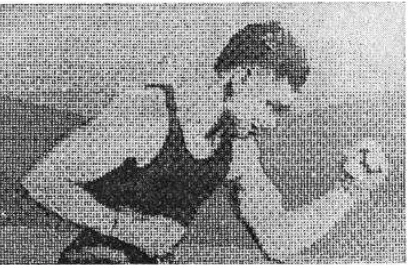
Figure 1.1 : A digital picture produced in 1921 from a coded tape by a telegraph
printer with special type faces, (McFarlane, 1972). ... 2
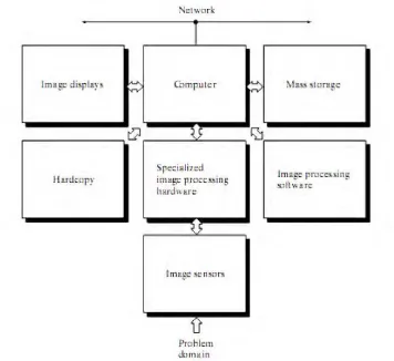
Figure 1.2 : Component of Digital Image Processing System ... 3
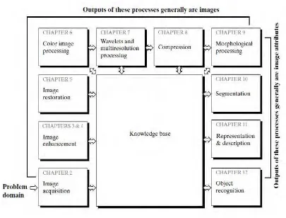
Figure 1.3 : Fundamental Steps in Digital Image Processing ... 4
Figure 2.1 : The overall system architecture ... 9
Figure 2.2: Letter sorting office ...10
Figure 2.3: Process of object’ recognition and sorting ...11
Figure 2.4: The detection and control process of system ...12
Figure 2.5: Schematic diagram of recognition system...13
Figure 2.6: Configure Diagram of the system ...14
Figure 2.7 : Computer Vision Based Tool Monitoring System ...15
Figure 2.8 : Experimental equipment for automatic surface defect detection of ...16
Figure 2.9 : Proposed model of vision based automated fruit grading and sorting ....17
Figure 2.10 : Conveyor unit 1, front side ...18
Figure 2.11: Conveyor unit 2, front side ...18
Figure 3.1 : Block Diagram of the image processing and sorting process ...20
Figure 3.2: Flow chart of the whole system ...21
Figure 3.3 : Flowchart of whole project. ...23
Figure 3.4 : Literature review flowchart ...24
Figure 3.5 : Methodology flowchart ...25
Figure 3.6 : PLC ladder diagram ...30
Figure 3.7 : The front screen of the FluidSIM software. ...32
Figure 3.8 : Example of DraftSight interface. ...32
Figure 3.9 : Automated process ...33
Figure 3.10 : Manual page to do troubleshooting ...33
Figure 3.11 : The Input and Output list of the overall project...34
Figure 3.12: The Input Mapping in CX-Programmer ...35
Figure 3.13: The Output Mapping in CX-Programmer ...35
Figure 3.14: The alarming part in ladder diagram ...36
Figure 3.15 : Automated process ...37
Figure 3.16: Sorting object type A ...37
Figure 3.17: Sorting object type B ...38
Figure 3.18 : Simulation for actuator 1 ...39
Figure 3.19 : Simulation for actuator 2 ...39
Figure 3.20: Power Distribution 1 ...40
Figure 3.21: Power Distribution 2 ...40
xvi
Figure 3.23: Output connection ...41
Figure 4.1: The program and result of edge segmentation...55
Figure 4.2 : The result that show the connected regions ...55
Figure 4.3 : Colour segmentation for the green cuboid part 1 ...56
xvii
LIST OF TABLES
Table 3.1 : The differences between three types of photoelectric sensors ...27
Table 3.2 : Extra Features of HALCON ...31
Table 3.3 Overall Cost ...41
Table 4.1: Details for calculate Average Hourly Plant Production Rate, Rpph ...48
Table 4.2 : Spreadsheet 1 ...52
Table 4.3 : Spreadsheet 2 ...52
Table 4.4 The accuracy of project for product A ...53
xviii
LIST OF SYMBOLS AND ABBREVIATIONS
IO - Input and Output
Tc - cycle time, min/pc;
To - time of the actual processing or assembly operation, min/pc;
Th - handling time, min/pc;
Tt - average tool handling time, min/pc. Rp - hourly production rate, hr/pc; Tp - average processing time, min/pc; TB - batch processing time, min/pc;
Q - batch quantity, pc/batch;
TSU - setup time to prepare the machine for the batch,
Rpph - average hourly plant production rate;
Rpij - production rate of machine i when processing part j; fij - the fraction of time during the period that machine i
is processing part style j;
noj - the number of operations required to produce part j; Tno - Non-operation time, min
MLT - Manufacturing Lead Time
WIP - Work-in-Process
-1
CHAPTER 1
INTRODUCTION
1.0 Introduction
This chapter provides an introduction about this whole project. It starts with general information and background about image processing, problem statement. It will also cover the objective, problem statement and scope for the overall project.
1.1 Project Background
The project is about creating teaching tools for primary and secondary students to learn and know about the systems that used in industry such as sorting process and how it is operated. As we know, the industry is moving towards automation and robotics, lots of labour works and controls are being replaced by using advance system and machine. One of the labour process that have being replace by technology is sorting process. The purpose of the project is to provide a simple and lower cost teaching tools for primary or secondary students to learn about the sorting process in the real industrial. The students can expose earlier to the machines and systems that are using in the real industry. They will know how the sorting process is operated, how the image is process and how the conveyor belt is being control, thus it will increase the interest of the students in the field of engineering and technology.
1.1.1 Image Processing
2
dimension signal and applying standard processing techniques to obtain the best analysis result. In general, the objective of this process is to transform or analyze an image so that the new information of the image is made obvious. An image processing flow consist of enhancement process, restoration process, analysis, compression process and synthesizing.
1.1.2 History of Image Processing
The history of digital image processing started possibly for the problem of image transmission where it was applied in the newspaper industry. Earlier to this, analog images transported through air or ships which very time consuming and costly. To reduce transmission time, images were being digitized and transmitted through cable electronically. However, these techniques were found to involve loss of significant image information during reconstruction at the receiver end. Hence, suitable processes such as enhancement, restoration, encoding, and compression were developed. Figure 1.1 show a digital picture produced in 1921 from a coded tape by a telegraph printer with special type faces, (McFarlane, 1972).
3 1.1.3 Component of Image Processing
Figure 1.2 : Component of Digital Image Processing System
With reference to sensing, two elements are required to acquire digital images. The first element is a physical device that is sensitive to the energy radiated by the object we wish to image. The second is called a digitizer, is a device for converting the output of the physical sensing device into digital form. For example, in a digital video camera, the sensors produce an electrical output proportional to light intensity. The digitizer converts these outputs to digital data. Specialized image processing hardware usually consists of the digitizer plus hardware that performs other primitive operations, such as an arithmetic logic unit (ALU), which performs arithmetic and logical operations in parallel on entire images. This type of hardware sometimes is called a front-end subsystem.
4
specially designed computers are used to achieve a required level of performance.Software for image processing consists of specialized modules that perform specific tasks. A well-designed package also includes the capability for the user to write code that, as a minimum, utilizes the specialized modules. Mass storage capability is very important in image processing application as it provide storage space to store data. Image displays in Digital Image Processing System is mainly colour TV monitors that display images. As for hardcopy devices, they are used for recording images include laser printers, film cameras, inkjet units and CD-RO.
1.1.4 Fundamental Steps in Digital Image Processing
Figure 1.3 : Fundamental Steps in Digital Image Processing
5
Step 2. Image Enhancement: It is the process of manipulating an image so that the result is more suitable than the original for specific applications. Enhancement techniques are so varied, and use so many different image processing approaches. Step 3. Image Restoration: Image Restoration improving the appearance of the image and tend to be mathematical or probabilities models of image degradation. Step 4. Color Image Processing: Use the color of the image to extract features of interest in an image.
Step 5. Wavelets: Used in image data compression and pyramidal representation. Step 6. Compression: Techniques Compression for reducing the storage required to save an image and reducing the size of the image to transmit it ("JPEG Standard"), with suitable bandwidth required for transmission.
Step 7. Morphological Processing: Morphological Processing are the tools for extracting image' components that are useful in the representation and description of shape.
Step 8. Image Segmentation: Computer tries to separate objects from the image background. There are 3 kinds of Segmentation kinds: Autonomous Segmentation, Rugged Segmentation (long process to get successful solution) and Erratic Segmentation.
Step 9. Representation and Description: Representation makes a decision whether the data should be represented as a boundary or as a complete region
Step 10. Recognition and Interpretation: Recognition is the process that assigns label to an object based on the information provided by its descriptors.
Step 11. Knowledge base: controls the interaction between modules. The knowledge about a problem is coded into an image processing system in theform of a Knowledge base.
1.2 Problem Statement
6
enough. Furthermore, schools did not have suitable teaching kits to let the students to expose to the field of engineering and technologies.
1.3 Project Objectives
The objectives of this project are:
i. Develop a teaching tool to let students expose earlier to the system that used in industry.
ii. Demonstrate how the image is processed and how to determined the type of object.
iii. Demonstrate conveyor system and how to control it.
1.4 Problem Scope
The goal of this project is to develop simple teaching tools for primary or secondary students to learn about the sorting process in the real industrial. The final prototype will be consists of a conveyor system, a PC and a webcam while for the software, HALCON is used.
Detect the colour of the object (red and green) by using HALCON.
Detect the contour of the object (pyramid and cuboid) by using HALCON.
Sorting the object using PLC CP1E for teaching purpose.
1.5 Project Outline
7
knowledge and information about image processing such as the definition of image processing, the levels of image processing and the examples of the application of image filtering.
In Chapter 2, several references on previous research from various sources such as books, journals, Internet and previous projects about the application of image filtering was explained. In addition to that, several explanation on the types of image filtering techniques were also included.
Next, Chapter 3 explains about the method used in this project, from the beginning to the end of obtaining the results of the experiments done.
Chapter 4 comprises of the results and the brief explanations on the experiments are shown in the result section while the explanations about the image filtering functions regarding the experiments are shown in the discussion section.