DOI: 10.12928/TELKOMNIKA.v12i1.1973 123
Emergency Prenatal Telemonitoring System in Wireless
Mesh Network
Muhammad Haikal Satria*, Jasmy bin Yunus, Eko Supriyanto
Faculty of Health Science and Biomedical Engineering, Universiti Teknologi Malaysia, Skudai, Johor Bahru, Malaysia
*Corresponding author, email: [email protected]
Abstract
Telemedicine promises a great opportunity for health care service improvement. However, it has several issues for its implementation in certain area. They include communication service quality, infrastructure and operational cost. Since Wireless Mesh Network (WMN) is designed to reduce the infrastructure cost and operational cost, an investigation of network performance for implementation of telemedicine is required. In this paper, a simulation to investigate the wireless mesh network quality of service. Using network simulator 2, The QoS performance analysis was performed in different routing protocol scenarios of proposed system. It showed that OLSR protocol for Mesh Network maintained the time transfer of the EPT data. The field testing of the proposed system to measure the distance with various time has already been done. The infrastructure has been also implemented using low cost 5.8 GHz transceiver for backhauls and low cost 2.4 GHz transceiver for clients. Test result shows that the low cost telemedicine system is able to do real time communication between patient and medical staff with medical data rate up to 2 Mbps. It shows that telemonitoring system using wireless mesh network can give a low cost application in emergency time with acceptable medical data transfer quality.
Keywords: Telemedicine, Telemonitoring, Wireless Mesh Network
1. Introduction
Wireless communication technology has seen the fastest growth in the history to provide telemedicine innovation, boosted by deployment of enabling technology and technological advanced in signal processing, access and coverage area. The well established and emerging wireless technologies have tackled the location boundary from wired based telemedicine, where the parties need at specific place with the cable connection. The parties involved can tap into vital information anywhere and at any time within the wireless network coverage. Various wireless telemedicine solutions have been proposed and developed by adopting recent wireless technologies.
Most proposed solutions were based on commercial off-the-shelf wireless technologies, with enhancements on flexibility and deliverability on heterogonous data. The use of commercial network services, such as cellular and long term evolution (LTE), creates problems in integration between different global communication options and standards. Restricted scalability of the network provider may also limit the extent of telemedicine service especially in the low market area. The reliability and the quality of medical data exchanges in this network are very much reliant on the service level from network provider. The use of independent wireless network is needed to provide an open integrity for telemedicine service enhancement.
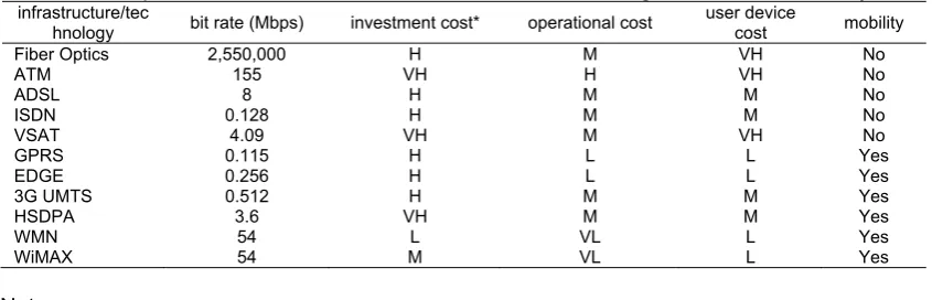
Table 1. Comparison of available network infrastructure/technologies for telemedicine system infrastructure/tec
hnology bit rate (Mbps) investment cost* operational cost
user device
VH = very high, H=high, M=medium, L=low, VL=very low
Each infrastructure has its own obstacle, particularly when they are implemented in the area where connectivity is the main issue. In the wired based infrastructure, Asynchronous Transfer Mode (ATM) and Multi Protocol Label Switching (MPLS) as a telemedicine backhaul, have limitation in mobility and scalability, even though both networks support Quality of Service (QoS) and have stability on delivering data [1].
The preliminary review of wireless application for telemedicine has been done in Pattichis et al. [2] by classifying technology into WLAN, global system for mobile communication (GSM) as cellular technology and satellite. Review in Ng et al. [3] has broaden the use of short-range wireless in sensor technology and birth of WIMAX to be used in telemedicine. Progress in cellular technology has initialized the wireless application on cellular technology into mobile-health (m-Health) by Istepanian et al. [4] and classified them into 2G and beyond 3G m-Health application. Although definition of m-Health in Istepanian et al. [4]and Micheli-Tzanakou et al.
[5] incorporates all types of wireless, almost all scientific paper in m-Health domain focused on proprietary cellular technology. The fragility of 3G UMTS network for telemedicine where the implementation costs are high and does not support QoS has been explored by Tan et al. [6].
The main general focus of this research is to provide a good telemedicine services at distance and with low cost implementation on single/multi-user and inter-communication domain. The use of commercial network services, for example cellular and LTE, creates problem in integration between different global mobile communication options and standards. It also resulting difficulties in m-health compatibility linkage between operators and network providers. Restricted scalability and proprietary technologies for cellular and LTE may also limit the expansion of the network in underserved areas. Satellite technology could provide the most wide coverage than other wireless technology, but the high-cost of communication link per used creates the drawback on implementing satellite in telemedicine area [7, 8].
The proliferation of low cost wireless mesh network (WMN) in a number of large scale implementation, e.g. MIT roofnet [9], has opened the door for independent telemedicine infrastructure. The Institute of Electrical and Electronics Engineers (IEEE) provides the work of emerging IEEE 802.11s standard for semi-infrastructure of wireless mesh network. The IEEE 802.11s has a self-organization characteristic, scalability in coverage area and its carrier technology solely based on independent and free license-exempt frequency spectrum. The 802.11s gives less backhaul connection to every wireless node in the network compared to the conventional wireless local area network (WLAN) deployment. It is a low cost network with the reduction of installation, commissioning and operational cost thereby achieving 70% saving compared to conventional approaches [10]. These criteria offer promises for the open implementation of cost-effective telemedicine services.IEE E 802.11s is suitable candidate to leverage telemedicine service with the lower cost technology.
(ER-LINK) worked on 365 square kilometer with 95% coverage area of the city of Tucson, Arizona, USA [11]. Unfortunately, due to its lack of operational fund, this project had been shut down since 2011 by the local government albeit the mesh infrastructure still in use daily [12]. This project involves the use of Open Link State Routing (OLSR) WMN type.
The other telemedicine infrastructure involving non-802.11s standard of WMN could be seen in Pirzada et al. [13] for the incident area infrastructure, the work from Yarali et al. [14] for the emergency application and triage infrastructure by Marti et al. [15]. However, most of the work performances, in terms of throughput and delay, degrade significantly as the source is located at an increasing number of hops away from the destination.
2. Scenario
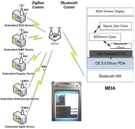
The scenario for low cost telemedicine system is based on our developed devices and infrastructure. The detailed of the development and its system could be seen in [16-18]. The general description is depicted in Figure 1, involved remote patients and health-care services that are equipped with medical data assistant (MDA). The MDA acquires the medical data using Medical Device Interface (MDI). MDI retrieves medical data from various medical devices.
Currently, the developed interface function to medical device has been done for electrocardiography machine (ECG), Doppler instrument, blood pressure monitor, ultrasound machine and stethoscope. The MDA are connected through wireless router and transceiver for data transmitting between patient and doctor. Two-way communication between patient and doctors is supported by camera and microphone. All of patient medical data are continuously recorded inside the server for diagnostic purposes.
Figure 1. Device configuration of low cost telemedicine infrastructure
Table 2. Result of Average output data rate [16]
devices data rates
good excellent
ECG 15 kbps 89 kbps
Doppler Instrument 40 kbps 160 kbps
Blood Pressure Monitor 1 kbps 2.4 kbps
Ultrasound Machine (Image) 104.6 kbps 400 kbps
Camera 136 kbps 2,020 kbps
Digital Stethoscope 40 kbps 160 kbps
Microphone 22.2 kbps 160 kbps
Total 358.8 kbps 2,991.4 kbps
Mesh Point as backhaul
The field testing has been done to investigate the network performance between remote patient MDA and the reliability of system. The network performance including signal quality of outdoor infrastructure, the outdoor maximum data rate that can be achieved and the MDI capacity has been tested. The reliability system also has been tested especially against the interference and weather changing in long time duration.
Parameters for the WMN outdoor backhaul are described in Table . The operational frequency of 5.750 GHz has been used to overcome distance and obstacles between backhaul connections.
The measurement is done for 7 days at 3 WMN backhaul using The Dude network monitor from Mikrotik™. As in Figure 2, the snapshot of the running monitoring measurement with sampling rate 1 second. The performance testing result shown in Table 11 is the average value for each low cost telemedicine backhaul at 1.2 km distance. The result shows the noise rate varies from its receiver sensitivity. The average signals for each backhaul in open space area with clear weather are in range -26 - -28 dBm. This gives the SNR values of 72 dB for low SNR and 82 dB for high SNR.
Table 3. Technical specification of WMN Backhaul
parameter value
Interface Card W-miniPCI card 100 Mw
Antenna Connector Low loss cable LM58
Table 4. Performance testing of each backhaul at 1.2 km
Table 5 shows the average values from connection measurement in each number of hops. Hop is counted from the user in location 1 to the destination in other location. The data rate was calculated from the average of data rate of each user. Testing results shows that the low cost telemedicine infrastructure within 3 hops on 3.4 km distance could fulfill the requirement of medical data rate of more than 2.8 Mbps for excellent quality of medical data. Moreover, the attenuation of weather and obstacles, such as building and tree) has decreased the SNR value into low than 72 dB in distance of 1.2 km. High data rate has also gave the impact on the attenuation of the signals, which could give the impact on the SNR value.
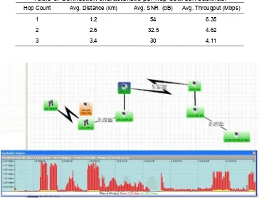
Table 5. Connection characteristic per hop between backhaul Hop Count Avg. Distance (km) Avg. SNR (dB) Avg. Througput (Mbps)
1 1.2 54 6.35
2 2.6 32.5 4.62
3 3.4 30 4.11
Figure 2. Snapshot of WMN backhaul measurement
3. Performance Analysis
The objective of this paper is to provide Wireless Mesh Network as the backhaul for remote patients in distance from healthcare personnel. This means the longer-range transmission is required with the high data rate support. As describes in Chapter 2, the communication between MP that are out of the transmission range is done by using intermediate MP. Hence, the communication among these MPs could be done if each MP holds the information of the destination route through intermediate mp.
The limitation of the available testing device for MDA and the backhaul are the main factor to analyze this routing characteristic. Here, the utilization of ns3 simulation framework is selected as the best way to measure the impact of different routing protocols in wireless mesh network.
Four performance parameters were evaluated in this simulation. They are (1) end-to-end delay, (2) throughput, (3) jitter and (4) the percentage of packets loss at the receiver node.
It is difficult to directly measure the end to end delay, due to the unsynchronized nature of multi hop WMN. We estimate the end to end delay by the round trip time delay i.e., the delay from the source to the destination and back to the source. End to end delay in this simulation is given by:
∑
where:
T = End to end delay (ms).
Tend = Time of packet received (ms).
Tstart = Time of packet sent (ms).
The throughput λ) value is measured from packet arrival rate at the mesh clients. The packet average end to end delay has to remain finite. Equation of throughput T) for WMN is given by:
T=
T = Throughput (Kbps) P (n) = Number of packet (Kb)
D = End to end delay (s)
The packet loss parameter is measured by the percentage of the number of loss data packets sent by receiver to the destination.
%
where:
PLR = Packet loss ratio (%)
fsDrops = Number of packets drop
numFs = Number of packets sent
Analysis of simulation results were evaluated for the system describes in section 4.3 in wireless mesh network based on four QoS parameters.
Experimentation Parameters
The simulation physical environment in table 6 describes the technical specification of WMN backhaul. A path loss model is based on Kun path Loss model [19] for wideband channel. The common path loss for open space model, such as Okumura-Hata, has coverage not more than 1.5GHz. The path loss model at 2.6GHz per distance is stated as:
6 log
This empirical model is a typical outdoor suburban and urban environment with uniform distance more than 1km and carrier frequency higher than 2.3GHz. The path loss exponent is 2.2 with a standard deviation of 9.3dB.
Table 6. Simulation parameters of General environment model
Parameter Values
Channel Model Propagation Delay Constant Speed
Propagation Lost Kun Path Loss Model
Carrier Frequency 2.4 GHz
System Loss Coefficient 1
Mesh Device Model Reception Gain 1 dB
Transmission Gain 1 dB
Transmission Power 25 dBm
Reception Noise Figure 7 dB
CCA Threshold -62 dBm
Energy Detection Threshold -96 dBm
Data Link Model Modulation Scheme OFDM
Fragmentation Threshold 2346 byte
MAC Packet Length 1500 byte
Slot duration 20 us
Number Slots per Frame 100 slots
Max Queue Size 100 Packets
MP Distance 1 Km
Routing Protocol HWMP,AODV and OLSR
Application Packet Size 1024 Bytes
Packet Rate Packet Rate 250 KBps
Link Transmission Rate
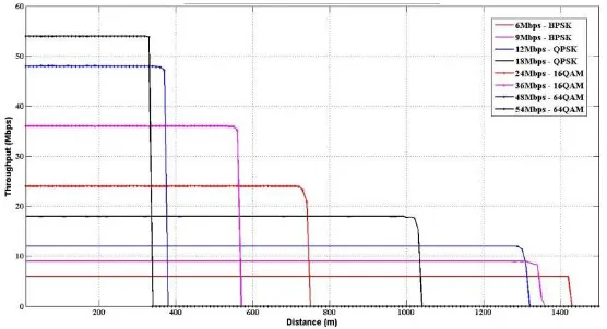
The data transmission rate for this experiment is determined by combining the modulation and encoding scheme. This research compares each modulation and encoding parameters to determine the data link model. The extended rate physical OFDM modulation scheme is then selected to provide the higher throughput with the longer distance traffic carrier for WMN. In this section, we only provide the impact of modulation-encoding scheme of 802.11g-ERPOFDM as shown in Figure 3.
Figure 3. Comparison of 802.11s-ERPOFDM transmission rates against distance
Hop Count
Figure 4. Comparison of 802.11s-OFDM transmission rates against number of MP hop
Routing Model
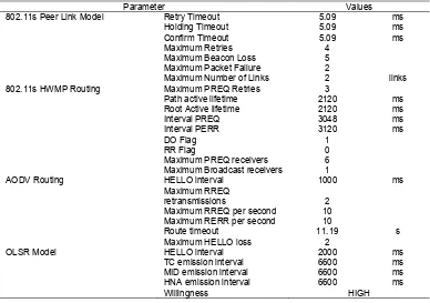
Each routing protocol had to be configured using the similar parameter value by taking into account their differences. This parameter adjustment assures the comparison between them is fair and their differences are come from the routing mechanism. Several individual tests for routing has been done and the selected parameters result are shown in Table 7.
Table 7 : Protocol Specific Parameters
Parameter Values
802.11s Peer Link Model Retry Timeout 5.09 ms
Holding Timeout 5.09 ms
802.11s HWMP Routing Maximum PREQ Retries 3
Path active lifetime 2120 ms
Root Active lifetime 2120 ms
Interval PREQ 3048 ms
AODV Routing HELLO interval 1000 ms
Maximum RREQ
retransmissions 2
Maximum RREQ per second 10
Maximum RERR per second 10
Route timeout 11.19 s
Maximum HELLO loss 2
OLSR Model HELLO interval 2000 ms
TC emission interval 6600 ms
MID emission interval 6600 ms
HNA emission interval 6600 ms
Willingness HIGH
the distance between peer MP. The changes on default DO and RR Flag are to overcome the flooding of control message effect and to make sure that the measurements is come from the data traffic from source and destination. By the same reason, the OLSR routing message emission interval and all control message lifetime in HWMP and AODV are increased.
All the loss parameters in each routing protocol are needed to be increased, especially in control message losses of HWMP and maximum hello loss of AODV. Their default values are extremely low for the long distance with exponential propagation loss. , The Willingness of OLSR is set to its highest value as there is no mobility aspect and MP is always act as intermediate MP.
Scalability Analysis
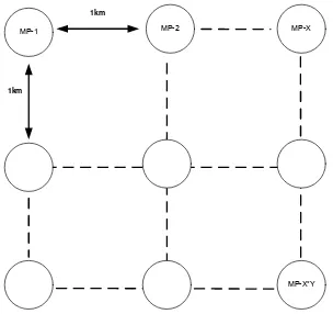
The scalability of protocol is analyzed by utilizing gird topology as describes in Figure 4.7. Three grid models are evaluated for 3 x 3 (9 MPs), 4 x4 (16 MPs) and 5 x 4 (25 MPs) with 1 kilometers of separation between MPs. This will guarantee that the path discovery could only be initialized by the closes intermediate MPs.
The numbers of data flows are established randomly between the nodes by scale of number MPs – 1. This will ensure the fairness of flow analysis for each protocol with durations per flow are exponentially seed in 50 seconds mean. The simulation is done in 800 seconds for each data rate sampling in a protocols. The packet size of each flow is set to 1024 bytes with an exponential increase of data rates start from 64Kbps to 1Mbps.
MP-1 MP-2 MP-X
MP-X*Y
1km
1km
Figure Error! No text of specified style in document..1 Topology for scalability performance
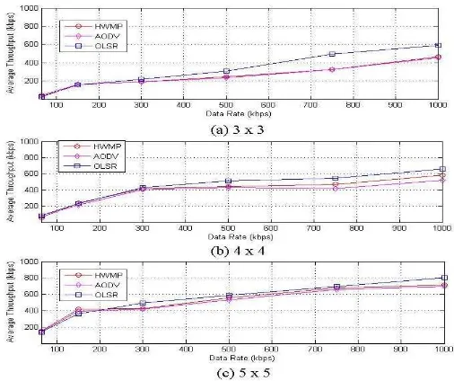
The graph analysis of throughput average is presented in figure 3.8. For the overall performance, OLSR gives slightly higher throughput than AODV and HWMP in a multi-hop network. While at the lower data rate up to 300 Kbps, the performance of three routing protocols had approximately the same average throughput, the performance of both HWMP and AODV decreased as the load increased for 25% from OLSR throughput.
Figure Error! No text of specified style in document..2 Performance analysis of throughput average for (a) 3x3 grid (b) 4x4 grid (c) 5x5 grid MPs
The comparison between AODV and HWMP are not giving any much differences, even the HWMP perform slightly better in greater grid. The airtime metric in HWMP detects any possibility error rates due to data traffic collusion. It gives the better link connection throughput 3% higher for the data flow than traditional distance vector of AODV.
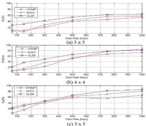
Figure Error! No text of specified style in document..3 Performance analysis of delay average for (a) 3x3 grid (b) 4x4 grid (c) 5x5 grid MPs
MP, waiting the request reply from destination. Hence, it takes amount of time to flow to the intended destination. OLSR gives the advantages in average 23% of having routes immediately available when needed due to its proactive nature and using only selected nodes MPR to retransmit control messages periodically. Although OLSR gives the complete table before delivering data transmission, its limitation to handle higher amount MPs is slightly reduced. The reactive mechanism requires a slow start to establish its path, but it stable when the amount of data is increase in time.
Figure Error! No text of specified style in document..4 Performance analysis of error rate average for (a) 3x3 grid (b) 4x4 grid (c) 5x5 grid MPs
The reactive comparison of AODV shows that delay difference is higher than HWMP. This is caused by the route discovery induced by both protocol. The AODV mechanism floods the route request message if there is no reply from the destination, especially in the congested path. It increases the contention windows of waiting reply in source MP before sending the data packet. The layer 2 mechanism in HWMP gives the priority of PREQ packet to be process in intermediate MP even the link is saturated with packet queuing. In some occasion, the higher delay of HWMP than AODV is caused by the airtime metric to avoid links being used and find the longer path even it has more delay.
In terms of packet error rate, figure 4.9 shows HWMP gives the best result. HWMP is calculating its routes using airtime metric where it senses the link error rate better than AODV and OLSR.
4. Conclusion
The variation for all performance parameter result shows that the proactive routing protocol of OLSR maintained the transfer time of telemedicine data traffic. The OLSR protocol gave the smallest time variation of delay and jitter rather than HWMP and AODV in various hop number and data rates. Overall, HWMP performance is more stable than other protocol. The higher data rate and hop count; HWMP could achieve almost the same performance than OLSR. In terms of the package loss rate, HWMP as the most effective routing protocol needs to be improved as the reliable communication protocol of telemedicine system data using WMN. This result indicates that further refinement of 802.11s based HWMP standard is required to reaches the performance for QoS traffic of telemedicine service.
References
[2] C. S. Pattichis, et al. Wireless telemedicine systems: an overview. IEEE Antennas and Propagation Magazine. 2002; 44: 11.
[3] H. S. Ng, et al. Wireless technologies for telemedicine. BT Technology Journal. 2006; 24: 130-137. [4] R. S. H. Istepanian, et al. M-Health Emerging Mobile Health Systems. Springer Science+Business
Media, Inc. 2006.
[5] E. Micheli-Tzanakou, et al. Ubiquitous M-Health Systems and the Convergence Towards 4G Mobile Technologies. M-Health, R. S. H. Istepanian, et al., Eds., ed: Springer US. 2006: 3-14.
[6] Y.-Y. E. Tan, et al. Fragility issues of medical video streaming over 802.11 e-WLAN m-health environments. 28th Annual International Conference of the IEEE Engineering in Medicine and Biology Society, New York. 2006.
[7] A. Jamal, et al. Role of Telemedicine during disaster: A Case Study. 9th International Conference on e-Health Networking, Application and Services, 2007 Taipei, Taiwan. 2007.
[8] Z. Wang and H. Gu. A review of telemedicine in China. Journal of Telemedicine and Telecare. 2009; 15: 7.
[9] J. Bicket, et al. Architecture and evaluation of the MIT Roofnet mesh network. 2005.
[10] S. Roch. Nortel's Wireless Mesh Network solution: Pushing the boundaries of traditional WLAN technology. Nortel Technical Journal. 2005; 2.
[11] X. Wang. Wireless mesh networks. Journal of Telemedicine and Telecare. 2008; 14: 401-403.
[12] N. Versel. Tucson shuts down ambulance-based telemedicine network. mobihealthnews.com, ed. Tucson: mobihealthnews.com. 2011.
[13] A. A. Pirzada, et al. SafeMesh: A wireless mesh network routing protocol for incident area communications. Pervasive and Mobile Computing. 2009; 5: 201-221.
[14] A. Yarali, et al. Wireless mesh networking: A key solution for emergency & rural applications. Advances in Mesh Networks, 2009. MESH 2009. Second International Conference on. 2009: 143-149. [15] R. Martí, et al. Providing early resource allocation during emergencies: The mobile triage tag. Journal
of Network and Computer Applications. 2009; 32: 1167-1182.
[16] E. Supriyanto and H. Satria. A novel low cost telemedicine system using wireless MESH network. 3rd South East Asian Technical University Consortium (SEATUC), Johor. 2009.
[17] I. H. Mulyadi, et al. Wireless medical interface using ZigBee and Bluetooth technology. Modelling & Simulation, 2009. AMS'09. Third Asia International Conference on. 2009: 276-281.
[18] I. H. Mulyadi. Hybrid zigbee-bluetooth communication protocol and adaptive bandwidth allocation algorithm for telemedicine application. Universiti Teknologi Malaysia, Faculty of Electrical Engineering. 2012.
![Table 2. Result of Average output data rate [16]](https://thumb-ap.123doks.com/thumbv2/123dok/243609.503253/4.595.130.466.670.746/table-result-average-output-data-rate.webp)