GSM-900 MOBILE JAMMER
MOHD ZAIDI BIN HUSIN
This report submitted in partial fulfillment of the requirement for the award of Bachelor of Electronic Engineering (Telecommunication Electronics) With
Honours.
Faculty of Electronic and Computer Engineering Universiti Teknikal Malaysia Melaka
FAKULTI KEJURUTERAAN ELEKTRONIK DAN KEJURUTERAAN KOMPUTER
BORANG PENGESAHAN STATUS LAPORAN
PROJEK SARJANA MUDA II
Tajuk Projek : GSM-900 MOBILE JAMMER
Sesi Pengajian : 2009/2010
Saya ………MOHD ZAIDI BIN HUSIN………..……….
mengaku membenarkan Laporan Projek Sarjana Muda ini disimpan di Perpustakaan dengan syarat-syarat kegunaan seperti berikut:
1. Laporan adalah hakmilik Universiti Teknikal Malaysia Melaka.
2. Perpustakaan dibenarkan membuat salinan untuk tujuan pengajian sahaja.
3. Perpustakaan dibenarkan membuat salinan laporan ini sebagai bahan pertukaran antara institusi
pengajian tinggi.
4. Sila tandakan ( √ ) :
SULIT*
(Mengandungi maklumat yang berdarjah keselamatan atau kepentingan Malaysia seperti yang termaktub di dalam AKTA RAHSIA RASMI 1972)
TERHAD* (Mengandungi maklumat terhad yang telah ditentukan oleh organisasi/badan di mana penyelidikan dijalankan)
TIDAK TERHAD
Disahkan oleh:
__________________________ ___________________________________
(TANDATANGAN PENULIS) (COP DAN TANDATANGAN PENYELIA)
Alamat Tetap: ………...
.………
Tarikh: ……… Tarikh: ………
i
DECLARATION
“This is hereby declared that all materials in this thesis are my own work and all the materials that have been taken from some references have been clearly
acknowledged in this thesis.”
Signature :………..
Author : Mohd Zaidi Bin Husin
“I hereby declare that I have this report and in my opinion this report is sufficient in terms of the scope and quality for the award of Bachelor of Electronic
Telecommunication Engineering With Honours.”
iii
ACKNOWLEDGEMENT
With the name of Allah, The Most Gracious and Merciful. Praise to Allah Almighty for giving me the will and strength to go through the entire this project and for giving me opportunity to complete this project report successfully.
First and foremost, I would like to express my deepest gratitude and appreciation to my respected supervisor, Miss Siti Normi Bt. Zabri@Suhaimi for her guidance, advices, supervision and encouragement in making the final project. The valuable and useful ideas that he had shared with me during the project period are very much appreciated.
Next, I would also like to convey my thanks to all lecturers that helped me directly or indirectly, for facilitating me in the preparation before this project and for spending his precious time and efforts in evaluating my work. For leading me their hands in assisting my project.
Special thanks also to my beloved parents, family members and friends for their help and supports in producing this report.
ABSTRACT
The report that produce by the student by their own initiative and own creativity to make sure the report are perfect and complete with all the result of the project. This report contents all the study by student to make sure the project finish on time. All the content is come from the design of the project. The content form the another engineering book also allowed to which are use to finish the project.
This project are design a GSM jammer is a device that transmit signal on the same frequency at which the GSM system operates, the jamming success when the mobile phones in the area where the jammer is located are disabled. This project is mainly intended to prevent the usage of mobile phones in places inside its coverage without interfering with the communication channels outside its range, thus providing a cheap and reliable method for blocking mobile communication in the required restricted areas only.
v
ABSTRAK
Buku laporan ini merupakan sebuah buku laporan yang dihasilkan oleh penuntut dengan inisiatif dan daya kreatif.Buku yang dihasilkan hendaklah berkaitan dengan apa yang dipelajari serta apa yang dilakukan oleh penuntut ketika menyiapkan projek.Semua isi kandungan yang terdapat dalam buku ini merupakan apa yang telah dipelajari dan diperolehi sepanjang menyiapkan projek ini.Kandungan dari buku-buku kejuruteraan yang lain yang berkaitan juga diambil sebagai melengkapkan lagi isi kandungan.
Projek yang dihasilkan iaitu GSM jammer adalah merupakan suatu peranti yang menghantar isyarat pada frekuensi yang sama di mana sistem GSM beroperasi. GSM dapat halang frekuensi telefon sekiranya jammer yang digunakan berada dalam kawasan yang aktif. Projek ini dihasilkan adalah untuk menghalang penggunaan telefon di tempat-tempat di dalam liputan tanpa mengganggu pusat komunikasi, selain dapat menghalang komunikasi pada kawasan lain.
TABLE OF CONTENTS
TITLE PAGE
Declaration
Acknowledgement Abstract
Abstrak
List Of Figures
i iii iv v ix
I INTRODUCTION
1.1Overview
1.2Problem Statement 1.3Project Objective 1.4Scope Project
1.5Technical Parameters
vii
TITLE PAGE
II LITERATURE REVIEW
2.1Introduction 2.2Operation
2.3Mobile Jammer Techniques 2.3.1Type “A” Device : Jammer
2.3.2Type “B” Device : Intelligent Cellular Disablers 2.3.3Type “C” Device : Intelligent Beacon Disablers
2.3.4Type “D” Device :Direct Receive & Transmit Jammers 2.3.5Type “E” Device : EMI Shield – Passive Jamming 2.4 GSM-Mobile Jamming Requirement
2.5 Design & Implementations of GSM Mobile Jammer 2.5.1 IF-Section
2.5.1.1 Triangular Wave Generator 2.5.1.2 Noise Generator
2.5.1.3 Signal Mixer and DC-Offset Circuits 2.5.2 RF-Section
2.5.2.1 Voltage Controlled Oscillator 2.5.2.2 RF Power Amplifier
2.5.2.3 Antenna 2.6 Conclusion 5 6 7 7 8 9 10 10 11 14 15 16 18 20 22 25 26 28 32 III METHODOLOGY
3.1Power Supply 3.2IF Section 3.3RF Section
3.4Procedure to aching the circuit schematic
TITLE PAGE
IV RESULT AND DISCUSSION
4.1 Introduction 4.2 Expected result
4.2.1 IF-Section 4.2.2 RF-Section
4.3 Process Testing 44 44 45 47 49
V CONCLUSION
5.1Conclusion 50
VI FUTURE DEVELOPEMENT
ix
List of Figures
NO. TITLE PAGE
2.1 Block diagram of GSM Jammer 2.2 Block diagram of IF Section 2.3 Timer connected as Oscillator 2.4 The output voltage on Cext 2.5 Noise Generator Schematic
2.6 White-noise generator output spectrum 2.7 OP-Amp Summer Circuit
2.8 Positive Diode-Clamper with bias 2.9 Circuit Schematic of IF Section 2.10 Block Diagram of RF-Section
2.11 Internal Block Diagram of MAX2623 IC
2.12 Typical biasing Configuration for the MAR-4SM 2.13 Design of MAR-4SM on AppCAD
2.14 T-Network Attenuator 2.15 RF PCB Layout
2.16 Circuit Schematic of RF Section
14 15 16 18 19 19 20 20 21 22 25 26 27 27 29 30
3.1 Block diagram of Power Supply 3.2 Circuit Schematic of Power Supply 3.3 Circuit Schematic of IF Section
3.4 Circuit Schematic of IF Section on the software Protel DXP 2004
3.5 Convert the IF-Section to the PCB Board 3.6 Circuit Schematic of RF Section
NO. TITLE PAGE
3.7 Circuit Schematic of IF Section on the software Protel DXP 2004
3.8 Convert the RF-Section to the PCB Board
39
39
4.1 Power supply circuit.
4.2 Circuit Schematic of IF Section 4.3 Result (Simulation) of IF Section 4.4 Block Diagram of RF-Section 4.5 Circuit Schematic of RF Section 4.6 Result (Simulation) of RF Section
1
CHAPTER I
INTRODUCTION
1.1 Overview
A GSM jammer is a device that transmit signal on the same frequency at which the GSM system operates, the jamming success when the mobile phones in the area where the jammer is located are disabled.
Mosques are example for the places that mobile jammer would be a great solution, although mosques asks politely from prayers to disable their mobile phone during the prayer, some people forget and the ringing phone of their mobile phone become very annoying.
1.2 Problem Statement
Due to an always growing demand, several solutions are currently under investigation in order to improve the capacity of current mobile communication systems, among which the exploitation of space diversity.
If uplink processing at the base station can be grounded on the availability of direct information about the concerned uplink channel (by the mean of a training sequence or blind methods), downlink processing encounters more severe difficulties: no information about the downlink channel is available at the base station prior to data transmission. We shall focus on that point, and proceed through several steps.
First of all, the problem statement will give us the opportunity to remind shortly how smart antennas can reduce ccI or handle space diversity multiplexing. Then notations will be introduced, and models of both uplink and downlink channels will be derived, highlighting their eventual similarities or differences, and the induced difficulties.
1.3 Project Objective
There are objectives of Mobile Jammer:
3
2) To block all kinds of mobile phones ringing sound at all places such as Banks, mosques, libraries, movie theaters, meeting rooms and others.
3) Effectively disable mobile phones within the defined regulated zones without causing any interference to other communication.
4) Directly communication with the GSM provider to block the service.
1.4 Project Scopes
Cell phones are full-duplex devices, which mean they use two separate frequencies, one for talking and one for listening simultaneously. Some jammers block only one of the frequencies used by cell phones, which has the effect of blocking both. The phone is tricked into thinking there is no service because it can receive only one of the frequencies.
The scopes of the Jammer :
1) It can restrict the mobile phone signal which 30m~70m & up in diameter and 200 meters far from the transmitting station.
2) It only shields mobile phone signals, but has no influence on other electronic equipments, audio equipments and human bodies.
3) It is easily installed and the connector plugs is the only one what is needed to install.
4) It saves the electric energy.
1.5 Technical Parameters
Technical parameters:
1) Working frequency : 935 MHz – 960 MHz
2) Working frequency band : GSM 900
3) Power Input : 240 V
4) Dimensions : 210 (L) * 135 (W) * 45 (H)mm
5) Antenna : Helical antenna (Omni directional radiation pattern)
Jammers can broadcast on any frequency and are effective against AMPS, CDMA, TDMA, GSM, PCS, DCS, iDEN and Nextel systems.
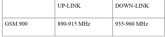
[image:16.612.145.486.434.512.2]The GSM transmission frequencies band are presented:
Table 1.1 GSM 900 Frequency Bands
UP-LINK DOWN-LINK
5
CHAPTER II
LITERATURE REVIEW
2.1 Introduction
A GSM Jammer is a device that transmit signal on the same frequency at which the GSM system operates, the jamming success when the mobile phones in the area where the jammer is located are disabled.
Communication jamming devices were first developed and used by military. Where tactical commanders use RF communications to exercise control of their forces, an enemy has interest in those communications. This interest comes from the fundamental area of denying the successful transport of the information from the sender to the receiver.
2.2 Operation
Jamming devices overpower the cell phone by transmitting a signal on the same frequency as the cell phone and at a high enough power that the two signals collide and cancel each other out. Cell phones are designed to add power if they experience low-level interference, so the jammer must recognize and match the power increase from the phone. Cell phones are full-duplex devices, which mean they use two separate frequencies, one for talking and one for listening simultaneously. Some jammers block only one of the frequencies used by cell phones, which has the effect of blocking both. The phone is tricked into thinking there is no service because it can receive only one of the frequencies. Less complex devices block only one group of frequencies, while sophisticated jammers can block several types of networks at once to head off dual-mode or tri-mode phones that automatically switch among different network types to find an open signal. Some of the high-end devices block all frequencies at once and others can be tuned to specific frequencies.
7
A jamming device transmits on the same radio frequencies as the cell phone, that is 900MHz disrupting the communication between the phone and the cell-phone base station in the town.
It is a called a „denial-of-service attack‟. The jammer denies service of the radio spectrum to the cell-phone users within range of the jamming device. Older jammers sometimes were limited to working on phones using only analog or older digital mobile phone standards. Newer models such as the double and triple band jammers can block all widely used systems (AMPS, iDEN, GSM, etc) and are even very effective against newer phones which hop to different frequencies and systems when interfered with. As the dominant network technology and frequencies used for mobile phones vary worldwide, some work only in specific regions such as Europe or North America.
The power of the jammer's effect can vary widely based on factors such as proximity to towers, indoor and outdoor settings, presence of buildings and landscape, even temperature and humidity play a role. There are concerns that crudely designed jammers may disrupt the functioning of medical devices such as pacemakers. However, like cell phones, most of the devices in common use operate at low enough power output (<1W) to avoid causing any problems.
2.3 MOBILE JAMMER TECHNIQUES
2.3.1 Type "A" Device:JAMMERS
transmitting calls. This type of device transmits only a jamming signal and has very poor frequency selectivity, which leads to interference with a larger amount of communication spectrum than it was originally intended to target. Technologist Jim Mahan said, “There are two types. One is called brute force jamming, which just blocks everything. The problem is, it‟s like power-washing the airwaves and it bleeds over into the public broadcast area. The other puts out a small amount of interference, and you could potentially confine it within a single cell block. You could use lots of little pockets of small jamming to keep a facility under control.”
2.3.2 Type “B” Device: INTELLIGENT CELLULAR DISABLERS
Unlike jammers, Type “B” devices do not transmit an interfering signal on the control channels. The device, when located in a designated „quiet‟ area, functions as a „detector‟. It has a unique identification number for communicating with the cellular base station. When a Type “B” device detects the presence of a mobile phone in the quiet room; the „filtering‟ (i.e. the prevention of authorization of call establishment) is done by the software at the base station.
9
It should be noted that the Type “B” detector device being an integral part of the cellular/PCS systems, would need to be provisioned by the cellular/PCS service providers or provisioned by a third-party working cooperatively with full support of the cellular/PCS service providers.
2.3.3 Type “C” Device: INTELLIGENT BEACON DISABLERS
Unlike jammers, Type “C” devices do not transmit an interfering signal on the control channels. The device, when located in a designated „quiet‟ area, functions as a „beacon‟ and any compatible terminal is instructed to disable its ringer or disable its operation, while within the coverage area of the beacon. Only terminals which have a compatible receiver would respond and this would typically be built on a separate technology from cellular/PCS, e.g., cordless wireless, paging, ISM, Bluetooth. On leaving the coverage area of the beacon, the handset must re-enable its normal function.
This technology does not cause interference and does not require any changes to existing PCS/cellular operators. The technology does require intelligent handsets with a separate receiver for the beacon system from the cellular/PCS receiver. It will not prevent normal operation for incompatible legacy terminals within a “quiet” coverage area, thus effective deployment will be problematic for many years.
2.3.4 Type “D” Device: DIRECT RECEIVE & TRANSMIT JAMMERS
This jammer behaves like a small, independent and portable base station, which can directly interact intelligently or unintelligently with the operation of the local mobile phone. The jammer is predominantly in receiving mode and will intelligently choose to interact and block the cell phone directly if it is within close proximity of the jammer.
This selective jamming technique uses a discriminating receiver to target the jamming transmitter. The benefit of such targeting selectivity is much less electromagnetic pollution in terms of raw power transmitted and frequency spectrum from the jammer, and therefore much less disruptive to passing traffic. The jam signal would only stay on as long as the mobile continues to make a link with the base station, otherwise there would be no jamming transmission – the technique forces the link to break or unhook and then it retreats to a passive receive mode again.
This technique could be implemented without cooperation from PCS/cellular providers, but Could negatively impact PCS/cellular system operation. This technique has an added advantage over Type B in that no added overhead time or effort is spent negotiating with the cellular network. As well as Type B, this device could discriminate 911 calls and allow for breakthroughs” during emergencies.
2.3.5 Type “E” Device: EMI SHIELD - PASSIVE JAMMING
11
With current advances in EMI shielding techniques and commercially available products one could conceivably implement this into the architecture of newly designed buildings for so-called “quiet-conference” rooms. Emergency calls would be blocked unless there was a way to receive and decode the 911 transmissions, pass by coax outside the room and re-transmitted.
This passive configuration is currently legal in Canada for any commercial or residential location insofar as DOC Industry Canada is concerned, however municipal or provincial building code by- laws may or may not allow this type of construction.
2.4 GSM – MOBILE JAMMING REQUIREMENTS
Jamming objective is to inject an interference signal into the communications frequency so that the actual signal is completely submerged by the interference. It is important to notice that transmission can never be totally jammed - jamming hinders the reception at the other end. The problem here for the jammer is that only transmitters can be found using direction finding and the location of the target must be a specific location, usually where the jammer is located and this is because the jamming power is never infinite. Jamming is successful when the jamming signal denies the usability of the communications transmission. In digital communications, the usability is denied when the error rate of the transmission cannot be compensated by error correction. Usually a successful jamming attack requires that the jammer power is roughly equal to signal power at the receiver. The effects of jamming depend on the jamming-to-signal ratio (J/S), modulation scheme, channel coding and interleaving of the target system. Generally Jamming-to-Signal ratio can be measured according to the following Equation.
Pj= jammer power Pt= transmitter power Gjr= antenna gain from jammer to receiver Grj= antenna gain from receiver to Jammer Gtr= antenna gain from transmitter to receiver Grt= antenna gain from receiver to transmitter Br= communications receiver bandwidth Bj= jamming transmitter bandwidth
Rtr= range between communications transmitter and receiver Rjt= range between jammer and communications receiver Lj= jammer signal loss (including polarization mismatch) Lr= communication signal loss
The above equation indicates that the jammer Effective Radiated Power, which is the product of antenna gain and output power, should be high if jamming efficiency is required. On the other hand, in order to pr event jamming, the antenna gain toward the communication partner should be as high as possible while the gain towards the jammer should be as small as possible. As the equation shows, the antenna pattern, the relation between the azimuth and the gain, is a very important aspect in jamming.