RBFNN CONTROL OF A TWO-LINK FLEXIBLE
MANIPULATOR INCORPORATING PAYLOAD
M. Khairudin
Electrical Eng. Dept. Universitas Negeri Yogyakarta
Jln. Karangmalang, Yogyakarta 55281, Indonesia, Telp. +62 274 586168 e-mail: [email protected]
Abstrak
Paper ini menyajikan model dinamik dan kendali dari manipulator robot lengan fleksibel dua link. Model dinamik menggunakan teknik Lagrangian dan assumed mode method (AMM). Permasalahan yang sering terjadi dalam robot lengan fleksibel dua link adalah getaran sebagai effect gerakan lengan fleksibel dan penambahan beban yang tidak diprediksi. Penelitian sebelumnya banyak membahas model kendali untuk sistem ini tetapi sedikit membahas sistem kendali terhadap pengaruh penambahan beban. Simulasi pada penelitian ini dikembangkan untuk menguji model dinamik, sistem response pada hub dan titik ujung dari setiap link dalam fungsi waktu serta menampilkan keuntungan menggunakan RBFNN kontroler untuk mengatasi masalah getaran pada gerakan lengan fleksibel, tracking posisi yang akurat dan effect penambahan beban. Hasil RBFNN controller akan diverikasi dengan membandingkan hasil PID kontroler. Hasil menggunakan metode RBFNN menunjukkan overshoot yang lebih kecil, cepat mencapai steady state dan performa yang lebih baik dibandingkan dengan menggunakan PID controller.
Kata kunci: Model, RBFNN, robot lengan fleksibel dua link.
Abstract
This paper presents the dynamic modeling and control of a two-link flexible robot manipulator. A dynamic model of the system is developed using a combined Euler-Lagrange and assumed mode methods. The most problems of a two-link flexible manipulator are vibration of flexible link and unpredictable payload additional. Previous researchers have discussed control methods for this system; few presented the effect of a payload profile. The simulation in this research is performed to assess the dynamic model and system responses at the hub and end-point of both links are presented and analyzed in time domains and show the advantages using radial basis function neural network (RBFNN) controller for solving flexible link vibration, achieve high-precision position tracking, and payload effect robustness. The results achieved by the proposed controller are compared with conventional PID to substantiate and verify the advantages the proposed scheme and its promising potential in control of a two-link flexible manipulator. It is shown that smaller overshoot, quickly steady state response and tracking performance of the proposed controller is good profile and better than PID controllers.
Keywords: Modeling, RBFNN, two-link flexible manipulator.
1. INTRODUCTION
Flexible manipulators have several advantages over rigid robots: they require less material, are lighter in weight, consume less power, require smaller actuators, are more maneuverable and transportable, have less overall cost and higher payload to robot weight ratio [1]. These types of robots are used in a wide spectrum of applications starting from simple pick and place operations of an industrial robot to micro-surgery, maintenance of nuclear plants and space robotics [2].
Practically, a robot is required to perform a single or sequential task such as to pick up a payload, move to a specified location or along a pre-planned trajectory and place the payload. Previous investigations have shown that the dynamic behaviour of the manipulator is significantly affected by payload variations [4].
The main goal on the modeling of a two-link flexible manipulator is to achieve an accurate model representing the actual system behaviour. It is important to recognize the flexible nature and dynamic characteristics of the system and construct a suitable mathematical framework. The numerical analysis methods that are utilized include finite difference and finite element methods. Both approaches have been used in obtaining the dynamic characterization of single-link flexible manipulator systems incorporating damping, hub inertia and payload [5]. Performance investigations have shown that the finite element method can be used to obtain a good representation of the system [3]. De Luca and Siciliano [6] have utilised the AMM to derive a dynamic model of multilink flexible robot arms limiting to the case of planar manipulators with no torsional effects.
This paper presents the dynamic modeling and control of a two-link flexible robot manipulator. A payload is attached at the end-point of the second-link whereas hub inertias are considered at the actuator joints. System responses namely angular position and modal displacement are evaluated in both time and frequency domains. The work presented forms the basis of design of a suitable control method for two-link flexible manipulator systems using a radial basis function neural network. The controller used for achieving of high-precision position tracking. The RBFNN controller design maximizes the control performance guaranteeing a good precision when regulating the tip position of the two-link flexible manipulator in the presence of a large time-varying payload and parameter uncertainties [8] and [9]. The result of this method will compare using a PID controller.
2. RESEARCH METHODOLOGY
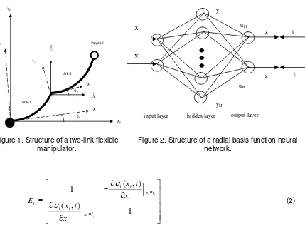
Figure 1 shows a structure of a two-link flexible manipulator system considered in these investigations. The links are cascaded in a serial fashion and are actuated by rotors and hubs with individual motors. The ith link has length
l
i with uniform mass density per unit lengthρ
i. The first link is clamped at the rotor of the first motor whereas the second motor is attached at the tip of the first link. E and I represent Young modulus and area moment of inertia of both links respectively. A payload is attached at the end-point of link-2. X0Y0 is the inertial co-ordinateframe, XiYi is the rigid body coordinate frame associated with the ith link and
X
iY
i)
)
is the moving coordinate frame.
θ
1 andθ
2 are the angular positions andv
i(
x
i,
t
)
is the transverse component of the displacement vector.M
p is an inertial payload mass with inertiaI
p at the end-point of link-2.The physical parameters of the two-link flexible manipulator system Mh2 is the mass considered at the second motor which is located in between both links, Jhiis the inertia of the
ith motor and hub. The input torque, τi(t) is applied at each motor and Gi is the gear ratio for the
ith motor. Both links and motors are considered to have the same dimensions. 2.1. The Dynamic Modeling of A Flexible Link System
This section focuses on the development of a combined Euler-Lagrange and AMM simulation algorithm characterizing the dynamic behaviour of the two-link flexible manipulator system as described by [6], [7]. The description of kinematics is developed for a chain of n
serially connected flexible links. Considering revolute joints and motion of the manipulator on a two-dimensional plane, the rigid transformation matrix,Ai, from Xi-1Yi-1 to Xi Yi can be written as
−
=
)
cos(
)
sin(
)
sin(
)
cos(
i i
i i
i
A
θ
θ
θ
θ
(1)
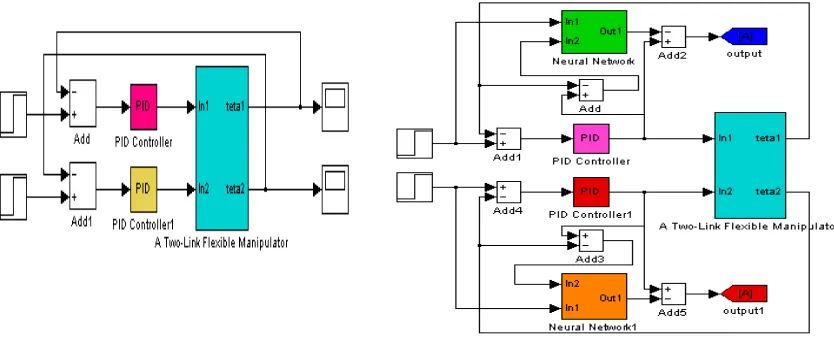
∂
∂
∂
∂
−
=
=
=
1
)
,
(
)
,
(
1
i i
i i
l x i
i i
l x i
i i
i
x
t
x
x
t
x
E
υ
υ
(2)
where
υ
i(
x
i,
t
)
is the bending deflection of the ith link at a spatial point xi (0 ≤xi≤li ).The global transformation matrix Ti transforming co-ordinates from X0Y0 to Xi Yi follow a
recursion as
i i i
i
T
E
A
T
=
−1 −1(3) To derive the dynamic equations of motion of a two-link flexible manipulator, the total energies associated with the manipulator system needs to be computed using the kinematics formulations. The total kinetic energy of the manipulator is given by
PL L
R
T
T
T
T
=
+
+
(4) where TR, TL and TPL are the kinetic energies associated with the rotors, links and the hubs, respectively.The total potential energy of the system due to the deformation of the link i by neglecting the effects of the gravity can be written as
i i
i i l
i n
i
dx
dx
x
d
EI
U
i2
2 2
0
)
(
)
(
2
1
=
∑
∫
υ
(5)
which bending deflections
υ
i(
x
i,
t
)
can be expressed as a superposition of mode-shapes. The co-ordinate vector consists of link positions, (θ1, θ2) and modal displacements (q11,q12, q21, q22). The force vector is F = {τ1, τ2,0, 0, 0, 0} T, where τ1 and τ2are the torques applied at the hubs of link-1 and link-2, respectively. Therefore, the dynamic equations of motion of a
two-Xi
X2
Y2
Y0
Yi
Link-1
Link-2
Payload
Θ2
θ1
i Xˆ
X0 i
Yˆ
Figure 1. Structure of a two-link flexible manipulator.
Figure 2. Structure of a radial basis function neural network.
input layer hidden layer output layer
z z u11
y
yM
uM
t
tJ
link flexible manipulator can be derived utilising the following Euler–Lagrange’s equations result, with i = 1 and 2 and j = 1 and 2 as:
i i i
L
L
t
θ
∂
θ
=
τ
∂
−
∂
∂
∂
∂
&
(6)and
0
=
∂
∂
−
∂
∂
∂
∂
ij ijq
L
q
L
t
&
(7)Considering the damping, the desired dynamic equations of motion of a two-link flexible manipulator can be obtained as
=
+
+
+
+
0
0
0
)
,
,
,
(
)
,
,
,
(
)
,
(
)
,
(
)
,
(
2 1 2 1τ
θ
θ
θ
θ
θ
θ
θ
θ
θ
θ
Kq
q
D
q
q
g
q
q
g
f
f
q
q
M
&
&
&
&
&
&
&
&
&
&
&
(8)where f1 and f2 are the vectors containing terms due to coriolis and centrifugal forces, M is the mass matrix and g1 and g2 are the vectors containing terms due to the interactions of the link angles and their rates with the modal displacements. K is the diagonal stiffness matrix and D is the passive structural damping.
2.2. Radial Basis Function Neural Network Background
Figure 2 shows a radial basis function neural network. The bell shaped curves in the hidden nodes indicate that each hidden layer node represents a bell shaped RBF that is centered on a vector in the feature space [8]. There are no weights on the lines from the input nodes to the hidden nodes. The input vector is fed to each m-th hidden node where it is put through the that nodes radial basis function
)]
2
/(
exp[
)
(
m 2σ
2m
m
f
x
x
c
y
=
=
−
−
(9)
where
x
−
c
m 2is the square of the distance between the input feature vector x and the center vectorc
m for that radial basis function.The values (ym) are the outputs from the radial basis functions. These radial basis
functions on a 2-dimensional feature space have the form shown in the simple graph below. The values equidistant from the center in all directions have the same values, so this is why these are called radial basis functions.
The outputs from the hidden layer nodes are weighted by the weights on the lines and the weighted sum is computed at each j-th output node as
∑
==
(
1
/
)
( 1, )M
m mj m
j
M
u
y
z
(10) The mean square error function that is to be minimized by adjusting the parameters {umj} is
similar to the one for back propagation NN except that this one is much simpler to minimize. There is only one set of parameters instead of two as was the case for back propagation NNs. Upon suppressing the index q has:
∑
∑
∑
= = =−
=
−
=
) , 1 ( 2 ) , 1 ( ) , 1 ( 2))
)
/
1
((
(
)
/
1
(
)
(
)
/
1
(
Jj j m M mj m
J
j j j
Thus
∑
=
−
−
=
∂
∂
∂
∂
=
∂
∂
) , 1
(
(
)](
/
)
)
/
2
[(
)
/
)(
/
(
/
J
j j j m
mj j j mj
M
y
z
t
J
u
z
z
E
u
E
(12)
There is still some missing information that have before it can implement an algorithm for training a RBFNN on a given data set {{x(q) : q = 1,...,Q}, {t(q) : q = 1,...,Q}} (here the feature vectors for training (the exemplar vectors) and paired with the target vectors by the index q). We still don’t know the center vectors {c(m) : m = 1,...,M} on which to center the radial basis functions. It also doesn’t know M and don’t know the spread parameter
σ
.This work presents techniques for achieving the control for a two-link flexible robot manipulator. First step is based on Proportional-Integral-Derivative (PID) controller, then its controlled by RBFNN controller based on PID controller. In this paper a PID controller used for a two link-flexible manipulator, the block diagram of a PID controller is shown in Figure 3.
Figure 3. The schematic of PID controller.
Figure 4. The structure of the neural network controller.
This is a type of feedback controller whose output, a control variable (CV), is generally based on the error (e) between some user-defined set point (SP) and some measured process variable (PV). Each element of the PID controller refers to a particular action taken on the error: Proportional: error multiplied by a gain, Kp. This is an adjustable amplifier. In many systems Kp is responsible for process stability: too low and the PV can drift away; too high and the PV can oscillate. Integral: the integral of error multiplied by a gain, Ki. In many systems Ki is responsible for driving error to zero, but to set Ki too high is to invite oscillation or instability or integrator windup or actuator saturation Derivative: the rate of change of error multiplied by a gain Kd. In many systems Kd is responsible for system response: too high and the PV will oscillate; too low and the PV will respond sluggishly. The designer should also note that derivative action amplifies any noise in the error signal. The Neural Network controller based on PID controller has been used for control of a two- link flexible manipulator systems, The block diagram of a Neural Network controllers based on PID controllers is shown in Figure 4 as taken from [8].
3. RESULT AND DISCUSSION
Otherwise, close loop system using a step input position allowing the manipulator. The output responses of the manipulator are taken from both angle rotation and modal displacement.
In this section, simulation results of the dynamic and intelligent control of the two-link flexible manipulator system are presented in the time domains. System responses are monitored for duration of 5 s, and the results are recorded with a sampling time of 1 ms. The input system using step input 0.4 rad for link-1 and step input -0.8 rad for link-2. Three system responses namely the angular positions, modal displacement and end-point acceleration at both links are obtained and evaluated.
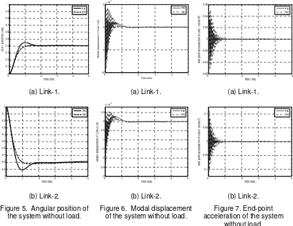
3.1 System without Payload
Figures 5, 6 and 7 show the angular positions, modal displacement and end-point acceleration responses of the RBFNN controller of two-link flexible manipulator without payload for both links comparing PID controller. It is noted that a steady-state angular position levels of 0.4 rad and -0.8 rad were achieved within 1.8 s for link-1 and link-2 respectively. The time responses specifications of angular position for link-1 were achieved within the settling time and overshoot of 0.89 s and 2.07 % respectively. On the other hand, the settling time and overshoot for link-2 were obtained as 0.86 s and 2.61 % respectively. The modal displacement responses of link-1 and link-2 were found to oscillate between -0.92x10⁻³ m to 0.43x10⁻³ m and -2.29x10⁻³ m to 0.55x10⁻³ m respectively. On the other hand, the end-point acceleration responses were found to oscillate between -0.05 to 0.05 m/s2 for link-1 and -0.14 to 0.12 m/s2 for link-2.
0 1 2 3 4 5
0 0.1 0.2 0.3 0.4 0.5 0.6 0.7 0.8 0.9 1 Time (ms) L in k -1 p o s it io n s ( ra d ) PID NN
0 1 2 3 4 5
-10 -5 0 5x 10
-4 Time (ms) M o d a l d is p la c e m e n t o f L in k -1 ( m ) PID NN
0 1 2 3 4 5
-0.06 -0.04 -0.02 0 0.02 0.04 0.06 Time (ms) E n d -p o in t a c c e le ra ti o n o f L in k -1 ( m /s e c 2) PID NN
(a) Link-1. (a) Link-1. (a) Link-1.
0 1 2 3 4 5
-1 -0.9 -0.8 -0.7 -0.6 -0.5 -0.4 -0.3 -0.2 -0.1 0 Time (ms) L in k -2 p o s it io n s ( ra d ) PID NN
0 1 2 3 4 5
-3 -2.5 -2 -1.5 -1 -0.5 0 0.5
x 10-3
Time (ms) M o d a l d is p la c e m e n t o f L in k -2 ( m ) PID NN
0 1 2 3 4 5
-0.1 -0.05 0 0.05 0.1 Time (ms) E n d -p o in t a c c e le ra ti o n o f L in k -2 ( m /s e c 2) PID NN
(b) Link-2. (b) Link-2. (b) Link-2.
Figure 5. Angular position of the system without load.
Figure 6. Modal displacement of the system without load.
Figure 7. End-point acceleration of the system
without load.
obtained as 0.64 s and 13.64 % respectively. The modal displacement responses of link-1 and link-2 were found to oscillate between -0.72x10⁻³ m to 0.12x10⁻³ m and -1.77x10⁻³ m to 0.29x10⁻³ m respectively. On the other hand, the end-point acceleration responses were found to oscillate between -0.04 to 0.03 m/s2 for link-1 and -0.07 to 0.08 m/s2 for link-2.
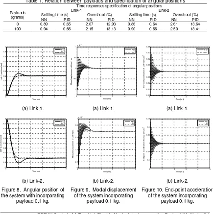
3.2. System with Payload
To demonstrate the effects of payload on the dynamic characteristics of the system, various payloads of up to 0.1 kg were examined. Figure 8, 9 and 10 show the system responses of the two-link flexible manipulator using RBFNN controller with payloads of 0.1 kg for link-1 and link-2 respectively. It is noted that the angular positions for link-1 same a steady state value towards the positive direction whereas the angular positions of link-2 same a steady state value in the negative direction with increasing payloads. For payloads of 0.1 kg the steady-state angular position levels for link-1 were obtained as 0.4 rad respectively whereas for link-2, these were obtained as -0.8 rad.
Table 1 shows comparisons the time response specifications of angular positions have shown significant changes with payload and without payload. With increasing payload, the system exhibits higher settling times and overshoots for both links. For link-1, the response exhibits an overshoot of 2.15 % with the settling time of 0.94 s for 0.1 kg respectively. For link-2, the response exhibits a percentage overshoot of 2.50 % with the settling time of 0.90 s for 0.1 kg payload.
Table 1. Relation between payloads and specification of angular positions Payloads
(grams)
Time responses specification of angular positions
Link-1 Link-2
Settling time (s) Overshoot (%) Settling time (s) Overshoot (%)
NN PID NN PID NN PID NN PID
0 0.89 0.65 2.07 12.93 0.86 0.64 2.61 13.64 100 0.94 0.66 2.15 13.13 0.90 0.66 2.50 13.41
0 1 2 3 4 5
0 0.1 0.2 0.3 0.4 0.5 0.6 0.7 0.8 0.9 1 Time (ms) L in k -1 p o s it io n s ( ra d ) PID NN
0 1 2 3 4 5
-1 -0.5 0 0.5
1x 10
-3 Time (ms) M o d a l d is p la c e m e n t o f L in k -1 ( m ) PID NN
0 1 2 3 4 5
-0.08 -0.06 -0.04 -0.02 0 0.02 0.04 0.06 0.08 Time (ms) E n d -p o in t a c c e le ra ti o n o f L in k -1 ( m /s e c 2) PID NN
(a) Link-1. (a) Link-1. (a) Link-1.
0 1 2 3 4 5
-1 -0.9 -0.8 -0.7 -0.6 -0.5 -0.4 -0.3 -0.2 -0.1 0 Time (ms) L in k -2 p o s it io n s ( ra d ) PID NN
0 1 2 3 4 5
-3 -2.5 -2 -1.5 -1 -0.5 0 0.5 1x 10
-3 Time (ms) M o d a l d is p la c e m e n t o f L in k -2 ( m ) PID NN
0 1 2 3 4 5
-0.1 -0.05 0 0.05 0.1 0.15 Time (ms) E n d -p o in t a c c e le ra ti o n o f L in k -2 ( m /s e c 2) PID NN
(b) Link-2. (b) Link-2. (b) Link-2.
Figure 8. Angular position of the system with incorporating
payload 0.1 kg.
Figure 9. Modal displacement of the system incorporating
payload 0.1 kg.
Figure 10. End-point acceleration of the system incorporating
Figure 8 until figure 10 show a modal displacements and end-point acceleration responses of the system with payloads respectively. It is noted with increasing payloads, the magnitudes of vibration of modal displacement increase for both links. In this case, the modal displacement responses of link-2 were found to oscillate between -2.55x10⁻³ m to 0.70x10⁻³ m for payloads of 0.1 kg respectively. However, the magnitudes of the acceleration responses decrease with increasing payloads. For link2 the responses were found to oscillate between -0.11 to 0.13 m/s2, for payloads of 0.1 kg respectively.
In this work, Figure 9 also show comparing RBFNN and PID controller. It is noted with increasing payloads, the magnitudes of vibration of modal displacement increase for both links. Using PID controller for link-1, the response exhibits an overshoot of 13.13 % with the settling time of 0.66 s for 0.1 kg respectively. For link-2, the response exhibits a percentage overshoot of 13.41 % with the settling time of 0.66 s for 0.1 kg payload.
In this case, the modal displacement responses of link-2 were using PID controller found to oscillate between -2.74x10⁻³ m to 0.65x10⁻³ m for payloads of 0.1 kg respectively. However, the magnitudes of the acceleration responses decrease with increasing payloads. For link-2 the responses were found to oscillate between -0.10 to 0.08 m/s2 for payloads of 0.1 kg respectively.
4. CONCLUSSION
The development of dynamic model and a RBFNN controller of a two-link flexible manipulator incorporating structural damping, hub inertia and payload have been presented. The model has been developed using a combined AMM and Euler-Lagrange approach. The RBFNN controller is efficient and easy to curry on. The RBFNN controller used has better then PID controller, as it can assume very different type of trajectory with training the controller for it. Simulations of the dynamic model have been carried out in the time where the system responses including angular positions, modal displacements and end-point acceleration are studied. The results show that the performance of the control system is improved greatly with the proposed controller, greatly decreasing the tip deflection of the second link and also enhancing the steady state accuracy for both links. Simulation results have shown that significant vibration occurs during movement of the system. It is found that the payload significantly affected the system behaviour in time response.
REFERENCES
[1]. Tokhi MO, Mohamed Z, Shaheed MH. Dynamic Characterisation of a Flexible Manipulator System. Robotica. 2001; 19: 571-580.
[2]. Dwivedy SK, Eberhard P. Dynamic Analysis of Flexible Manipulators: A Literature Review.
Mechanism and Machine Theory. 2006; 41:749-777.
[3]. Martins JM, Mohamed Z, Tokhi MO, Costa JS, Botto MA. Approaches for Dynamic Modeling of Flexible Manipulator Systems. IEE Proc-Control Theory and Application. 2003; 150: 401-411.
[4]. Mohamed Z, Tokhi MO. Command Shaping Techniques for Vibration Control of a Flexible Manipulator System. Mechatronics. 2004; 14: 69-90.
[5]. Aoustin Y, Chevallereau C, Glumineau A, Moog CH. Experimental Results for The End-Effector Control of a Single Flexible Robotic Arm. IEEE Transactions on Control Systems
Technology. 1994; 2: 371-381.
[6]. De Luca A, Siciliano B. Closed-Form Dynamic Model of Planar Multi-Link Lightweight Robots. IEEE Transactions on Systems, Man, and Cybernetics. 1991; 21: 826-839.
[7]. Subudhi B, Morris AS. Dynamic Modeling, Simulation and Control of a Manipulator with Flexible Links and Joints. Robotics and Autonomous System. 2002; 41: 257-270.
[8]. Araghi LF, Habibnejad MK, Nikoobin A, Setoudeh F. Neural Network Controller Based on
PID Controller for Two links- Robotic Manipulator Control. Proceedings of the World
Congress on Engineering and Computer Science (WCECS). San Francisco. USA. 2008. [9]. Tian L, Collins C. A Dynamic Recurrent Neural Network Based Controller for a