119
Development of Hexapod Robot with Manoeuvrable Wheel
M. Z. A. Rashid
1, M. S. M. Aras
1, A. A. Radzak
1, A. M. Kassim
1and A. Jamali
21
Universiti Teknikal Malaysia Melaka,
Hang Tuah Jaya, 76100 Durian Tunggal, Melaka, Malaysia
2 situation may be a remotely controlled by human or moves autonomously. Hexapod robot is one of the robots used in this situation because of its stability and flexibility during the motion on any type of surface. Hexapod robot is a robot that has six legs to walk or move. Since the robot has many legs, the robot is easily programmed to move around because it can be configured to many types of gait such as alternating tripod, quadruped and crawl. There are various designs of hexapod with certain function and advantages. In this research, a hexapod robot with manoeuvrable wheel is designed and developed. The purpose of the hexapod robot with manoeuvrable wheel is to ease the movement either on the flat surface or on the inclined surface. On the flat surface, the robot will move using the manoeuvrable wheel while on incline surface, the robot will climb using its legs. The decisions for the robot to use either wheel or legs are based on the sensory devices and algorithm develops at the controller attached to the robot.
Keywords: Autonomous, Manoeuvrable Wheel, Programmable, Hexapod
1. Introduction
The study of this project is to develop a new hexapod robot which is quite different from the existing product in the market today. This project is mainly about a hexapod robot with manoeuvrable wheel which is a combination of six legs robot and mobile robot. Hexapod robot is one of most statically stable and posses a great flexibility while standing or moving due to its movement using six legs that can easily manipulated. Mostly, for every robot created will be biologically inspired from behaviour of animal or insect especially on their walking behaviour. For the hexapod robot, cockroach and the stick insect are the most commonly used and have been ethologically (scientific study of animal behaviour) and neurophysiologically (study of nervous system function) are extensively studied by other people previously. In contrary the wheeled mobile robot is a mechanical wheels vehicle which has capability to move around the ground using motorized wheels. These two types of robot are classified as mobile robot. Therefore, it will be great to produce new mobile robot that has variety of movement either walking using its legs or manoeuvre using wheels.
2. Literature review
120
the institutions, individuals or companies. Furthermore, the section also explains about the hexapod robot that already published and available in the market nowadays.
2.1 Background of Hexapod Robot
A new technology emerges faster by adapting a new idea to develop a new design, prototype and new system control. One of the technologies that has high pace advancement such as the technology of hexapod robot which has increased from a simple function, size and weight to a various functions, bigger size and weight. LAURON is the example, a six-legged robot which has been developed at the Forschungszentrum Informatik Karlsruhe (FZI) in Germany. The first LAURON project was started in early 90s and continuously improved until the latest project called as LAURON IV [1].
The hexapod robots have various types and functions. Some of them are quite simple in the design and controller, while some of them possess a complex design and controller. For instance, in the tele-operation system, the robot [2] is capable to perform various tasks using a remote control at hazardous and narrow area which is cannot be covered by human beings. The operations are search and rescue, monitoring radiation hazard and planetary exploration. However, the most important factor to accomplish the task in a shortest time is the speed of the robot. The movement of robot by the wheels is faster than movement of the robot by legs. Thus, one method to increase the speed of hexapod robot is by equipped it with maneuverable wheels.
2.2 Literature Review of System Design
The system designs of hexapod robots from each journal have their own differences. RHex developed by [3] is a different robot compared to other hexapod robot because it is actuated by brushed DC motor. The motors that are used at this robot are Maxon type motor with a 33:1 planetary gearhead powered by a 24V NiMH battery. The design of the leg is one degree of freedom and half-circle. According to the author, the method is easy to build and maintain the robot and no sliding friction during spring displacement. This design is most suitable for stair climbing.
Another hexapod robot, Bill-Ant-P robot done by [4] is made of 6061 aluminum and carbon fiber sheets. It uses MPI MX-450HP hobby motors for its reliability, high torque, and affordability movement. The motor have 8.37kg-cm of torque, can rotate about a 60 degree in 0.18sec, and has a small internal dc motor consumes 1125mW of power at stall torque.
In the journal done by [5], a robot called as Gregor has been developed. The Gregor robot development model has Autodesk Inverter 9.0 to define properties of parts such as mass. Rhinocerus 2.0 software is used to coordinate of the constraints and model the robot that can be easily exported into the dynamic simulation environment which is also used the same software.
MSR-H01 hexapod developed by Micromagic System is built from 26 precision laser-cut 5053 aluminum body and leg components. It is controlled by using a p.Brain-HexEngine and used eighteen servomotors from three different types of servomotors. The link for the robot is Bluetooth with quality 99.2% from 17215 packets sent, 17083 packets are acknowledged [6].
Hexapod robot developed by [7] used Devantech SD-21 board to control 18 servos by interfaced with the preferred microcontroller, which is Arduino Decimilla board. The software that is used to control the servo controller is Matlab. In other to control the robot leg, Jacobian inverse matrix method is used to define the angles and leg position.
121
16-bit AVR ATmega128 and able communicates with external computers by RS232. The main controller communicated with the robot by sending and receiving data packets to the motors and sensors
The walking robot Ragno developed by [9] is 33 cm long and 30 cm wide and 2.15 kg weights. It has four layers control architecture where the first is at off-board to compute the appropriate control signal for all leg’s joint and send control commands to robots. The second layer is on-board control layer that interprets commands from first layer and sends to leg controllers. There are six leg controllers that work simultaneously and control the inputs send to them. The robot has a double axis accelerometer and a gyroscope to measure the trunk orientation in a 3D space. The on-board and off-board parts of the control system communicate by means of a Bluetooth connection.
2.3 Literature Review of Hexapod Robot Movement
The robot’s legs movement or method of forward motion using hexapod legs is called gait.
There are varieties of gaits available and the famous gait used by hexapod robot is the tripod gait. In the tripod gait, three feet of hexapod is always in contact with the ground for the whole time. For example, the hexapod robot that used the gait method is [10].
Method of movement for Gregor 1 hexapod robot designed by [7] is the locomotion control inspired from the biological paradigm of the Central Pattern Generators (CPG). CPGs are neural networks that produce rhythmic patterned outputs without sensory feedback and biological paradigm means medical model.
In the journal by [2], there are three types of robots motion. Those are walking mode, lifting mode and shifting mode which can be selected by the user. However, only the walking mode is selected in this subchapter to be explained further. The author used tripod gait is used because it is stable compared to other gaits for hexapod robot. The first step in gait control, the initial posture of all legs is decided, and the position of the leg tip is defined as the
“reference position”. Then, six cylinders of the legs movement are generated so as to be included in the work space with the center of the robotics base is set as the reference position. Thus, the center of rotation of the motion is obtained. Then, the diameter of each cylinder is reduced so that it may be proportional to the distance between the centre of robot (COR) and each reference position. The desired path of each leg is generated along the circumference of the cross section of the cylinder which is perpendicular to the line from the COR to the reference position and passes through the reference position. Finally, the angles of all joints are generated at every control period so that each leg tip might track the desired path and the center of body might have the provided velocity, and transmitted to the robot.
The hexapod robot in the research done by [8], the hexapod robot also use tripod gaits, the body of the robot and ground in parallel mechanism and supported by three legs. This journal is focused on the kinetics movement of robot and the locomotion system. It is about the calculation on how the hexapod robot moves. The important aspects taken into consideration are the inertial frame, locomotive referenced coordinate system of chassis and coordinate system on the coxa.
122
Dash robot by [12] can move at 11 body-lengths per second or 1.5 meters per second. The weights of entire system is 16.2 grams (10x5 cm body dimension) with include weight of battery, electronics, microcontroller, motor driver, and Bluetooth communication module. The alternating tripod gait is used with 10 cm wide and 5 cm tall of legs. When it moves, the center of mass follows a roughly sinusoidal trajectory, which is stable sinusoidal motion.
Two statically stable gaits is programmed for Ragno robot [9] that are exploits a simple crawl and a tripod-like gait. The crawl is used for lower speed by transfer one leg per time while tripod gait is the fastest stable gait with three legs placed on the ground at a time. The configuration of the robot’s gait is shown in Figure 1.
Figure 1. Tripod-like Gait Designed by [9]
With a single step length which is the distance between two consecutive footholds of one leg set to 50 mm, the average walking speed of the Ragno robot by using the tripod movement is 0.09 m/s.
3. New Physical Model of Hexapod Robot
This section discusses about the details on how the hexapod robot is being developed. The development starts by design and sketch a several design of hexapod robot with different aspect and criteria until to the design of the controller before the hexapod robot is being test.
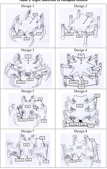
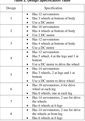
The designs of hexapod robot have been sketched in eight different designs and every design has it different criteria, specifications, shapes, advantages and disadvantages. The eight designs of the hexapod robots are shown in Table 1.
123 Table 1. Eight Sketches of Hexapod Robots
Design 1
Design 2
Design 3
Design 4
Design 5
Design 6
124 selected before it is drafted into a detail dimension and size. The method that is used to select the design is based on House of Quality because the comparison between each design can be clearly determined. In addition, every design has different specifications, aspects and shapes, and the best design defined based on the researcher’s own observation and opinion.
From all designs that have been sketched, the design 8 is selected as the best design because of the design possesses less overall weight. It only exploits fourteen servomotors to move either by using legs or wheel. The design of the maneuverable wheels and legs make the robot easy to move and climb. Besides that, the combination of the wheels and the legs will make the hexapod robot move more stable. This design has higher rating from the comparison that has been made.
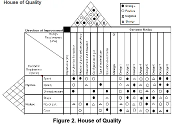
3.2 House of Quality
125
design in this project. The house of quality is a diagram that is used to define the relationship
between the customer needs and the product capabilities or requirements. This project’s house
of quality is shown in Figure 2.
Based on the House of Quality, there are two different requirement which are; design requirement and customer requirement. The measurement used in design requirement are by using wheel on the flat surface, total number of parts and servomotors, overall mass and dimension, configuration of gait, types of material use and selection of controller. The measurements used in customer design are speed, quality, stess or pressure, shape, number of part and cost. The rating of the hexapod robot’s design from positive strong, positive, negative, to strong negative is determined by the studied on the literature review of the
hexapod robot’s journals. The design requirement and customer requirement is also compared
to give a rating for the most important aspect to the less important.
Figure 2. House of Quality
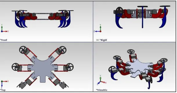
3.3 Hexapod Draft using Solidworks Software
After the best design is chosen, the size and dimension of the each part of the hexapod robot need to be determined so that it can be drawn using Solidworks software. The purpose of utilizing this Solidworks software is because Solidworks can provide a detail, real images and walkthrough overviews for demonstrating design. Solidworks is a fast drawing detailing software which can reduce time-consuming in the overall development process especially in true product detailing portion. It is not only just for drawing but also can be used to analyze the simulation, motion, animation, and other things. Faster analysis can be achieved by analyzing the entire structure to obtain the strength, stress, load, force and pressure of the selected material. Indeed, Solidworks support many types of files to import or export to other software format, for instance to .stl file which can be used at rapid prototyping machine (RPM).
126
one design to build a hexapod robot. The views of each part of the robot are shown in Figure 3 to Figure 6.
The design of each part is analyzed by using Solidwork’s simulationXpress to calculate the displacements, strains, and stresses of the system based on the material, fixtures, and loads. A material fails when the stress reaches a certain level on the material strength because each material has different stress levels. SimulationXpress uses linear static analysis, based on the Finite Element Method, to calculate stresses. Linear static analysis makes several assumptions to calculate stresses in the part. Using the displacements, SimulationXpress calculates the strains in various directions while using stress analysis, the forces and pressure is calculate base on material and fixture.
Stress is used to measure the strength of a material in how the material can stand without undergoes on physical change when pressure or force is applied. The formula use to calculate the stress is , which is F is force and A is cross sectional area. In addition, stress is dividing into two types that are tensile strength or known as fracture stress and yield strength or known as yield stress. Stress will cause strain which is the stretched of the object. The formula for strain is , which is is the original length and is the different of length
stretched. The relation between stress and strain will obtain Young’s modulus in order to measure the stiffness of a material. The formula is given by with units as N/m2 or Pa.
Figure 3. Hexapod Robot Isometric View Draft
127 Figure 5. Hexapod Front Leg’s View
Figure 6. Hexapod Middle Leg’s View
3.4 Component Selection
3.4.1 Selection of Motor
128
Figure 7. Servomotor C36R and C40R
Table 3. Servomotor Specification
Type C36R C40R
Gear material Plastic Plastic
Speed (sec/60deg) 0.16/4.8V, 0.14/6.0V
0.16/4.8V, 0.14/6.0V
Torque (Kg.cm) 3.5/4.8V, 4.5/6.0V 6.0/4.8V, 7.0/6.0V
Size (mm) 40.8x20.18x36.5 40.2x19.8x36
Weight (g) 36 38
Pulse width range 0.546ms to 2.4ms 0.54ms to 2.4ms
Rotation angle 180 degree 180 degree
Designed Closed feedback Closed feedback
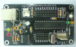
3.4.2 Selection of Controller
The controller used to control the servomotor is 16 channel servo controller (SC16A) as shown in Figure 8. By using this SC16A, the 14 servomotor can be controlled simultaneously in a single board. The controller also provides sample GUI software to control from computer. The size of dimension is 8.2cm x 4.7cm.
Figure 8. 16 Channel Servo Controller
129
3.4.3 Selection of Sensor
Sensor is a device use to sense something to control the movement of robot. In this project, the infrared sensor is chosen because it is high sensitivity, detection accuracy and process for experimental robots. There are two types of infrared sensor that is passive (PIR) and active (emit an IR beam and detect reflection). The active infrared sensor type is used for the hexapod robot because it can detect the presence of object in certain distance in front of the sensor. The sensor used as shown in Figure 9.
Figure 9. Distance Infrared Sensor
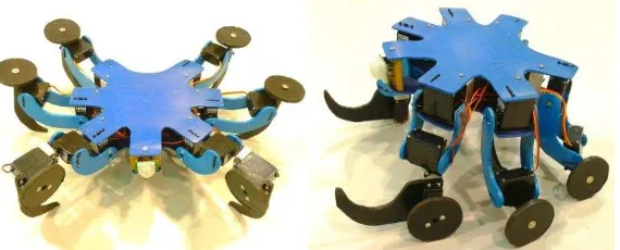
3.5 Hexapod Robot Hardware Model
The hardware of the hexapod robot is fabricated after the design and analysis on Solidwoks has been done. The hexapod robot is fabricated part by part using a few simple and low cost mechanical tools such as saw, grinder, hand drill, knife and ruler. When all parts have been fabricated, all the parts and components are assembled together to complete the hexapod robot. The hexapod robot hardware are shown in Figure 10.
Figure 10. Hexapod Robot using Legs and Wheels
3.6 Movement Selection
130
4. Result and Discussion
This section will discuss the result of hexapod robot have been done. The results cover the ideas that have been translated into sketches, design, programming, simulation controller and prototype. Several experiment and analysis in this project is to show how the problems are solved and the toughness of the robot developed.
4.1 Design Analysis
Every parts of hexapod robot is required to be analyzed to find out either it is strong enough to hold some force or pressure before the overall parts are assembled. Simulation using software is a way to reduce time and cost before the prototype is being fabricated. Thus, by using SimulationXpress that is provided inside SolidWorks software, the strength of the part that has been designed can be analyzed.
In this simulation, there are three types of analysis is created which are deformation, displacement and stress analysis. In the deformation analysis, the movement of the part when applied by some force or pressure can be animated. The effect can be seen and can be play in slow or fast motion. For the displacement, it is show to which area of the part is move from the initial condition. The high impact will give it higher displacement and more critical point. The color of the parts show the effect which is from less to high that is from blue to red. Different situation occur for stress analysis, the effect of color from blue to red show which area has less stress to higher stress.
4.1.1 Stress Analysis of Hexapod Robot Parts
Figure 11. Leg (Femur) Stress Analysis
131 Figure 13. Front Leg (Tibia) Stress Analysis
Figure 14. Leg (Tibia) Stress Analysis
132
Figure 16. Holder Stress Analysis
Figure 17. Wheel Stress Analysis
4.1.2 Displacement Analysis of Hexapod Robot Individual Parts
133 Figure 19. Front Leg (Femur) Displacement Analysis
Figure 20. Front Leg (Tibia) Displacement Analysis
134
Figure 22. Body Displacement Analysis
Figure 23. Holder Displacement Analysis
Figure 24. Wheel Displacement Analysis
5. Conclusion
135
selection of the robot has been successfully carried out. The robot is actuated using 14 servomotors including six wheels. This project also implemented by using PIC16F877A and programmed with MikroC software.
Acknowledgements
The authors want express appreciation to Universiti Teknikal Malaysia Melaka (UTeM) for sponsoring this project.
References
[1] E. Celaya and J. L. Albarral, “Implementation of A Hierarchical Walk Controller for the LAURON III Hexapod Robot”, Professional Engineering Publishing Limited, Institute of Robotics and Industrial Informatics, (2003), pp. 1-8.
[2] M. Kurisu, “A Study on Teleoperation System for a Hexapod Robot”, IEEEXplore, (2011), pp. 135-141. [3] E. Z. Moore, “Leg Design and Stair Climbing Control for the RHex Robotic Hexapod”, McGill University of
Canada, (2002), pp. 1-91.
[4] W. A. Lewinger, M. S. Branicky and R. D. Quinn, “Insect-Inspired, Actively Compliant Hexapod Capable of Object Manipulation”, Case Western Reserve University, Cleveland, USA, (2005), pp. 1-8.
[5] M. Calì, G. Fatuzzo, S. M. Oliveri and G. Sequenzia, “Dynamical Modeling And Design Optimization of A Cockroach-Inspired Hexapod”, University of Catania, (2007), pp. 1-10.
[6] Micromagic System Technical, “P.Brain-HexEngine V1.21 Configuration Guide”, Micromagic system, (2009), pp. 1-35.
[7] E. Burkus and P. Odry, “Autonomous Hexapod Walker Robot”, Polytechnical Engineering College, (2008), pp. 69-85.
[8] X. Duan, W. Chen, S. Yu and J. Liu, “Tripod Gaits Planning and Kinematics Analysis of a Hexapod Robot”, IEEE International Conference, (2009), pp. 1850-1855.
[9] D. Belter and P. Skrzypczynski, “A Biologically Inspired Approach To Feasible Gait Learning For A
Hexapod Robot”, Pozna´n University of Technology, Poland, (2009), pp. 1-16.
[10] Polulu Coorporation, “Sample project: Simple Hexapod Project”, Pololu Corporation, (2010), pp. 1-21. [11] M. M. Billah, M. Ahmed and S. Farhana, “Walking Hexapod Robot in Disaster Recovery: Developing
Algorithm for Terrain Negotiation and Navigation”, World Academy of Science, Engineering and Technology, (2008), pp. 1-6.
![Figure 1. Tripod-like Gait Designed by [9]](https://thumb-ap.123doks.com/thumbv2/123dok/568470.67215/4.612.151.449.228.425/figure-tripod-like-gait-designed-by.webp)