i
HOME APPLIANCES SMS CONTROLLER
ZARIF BIN CHE HASHIM
This report is submitted in partial fulfillment of the requirements for the award of Bachelor of Electronic Engineering (Computer Engineering) With Honours
Faculty of Electronic and Computer Engineering Universiti Teknikal Malaysia Melaka
iii
“I hereby declare that this report is the result of my own work except for quotes as cited in the references”
Signature : ……… Author : Zarif Bin Che Hashim
iv
“I hereby declare that I have read this report and in my opinion this report is sufficient in terms of the scope and quality for the award of Bachelor of Electronic
Engineering (Computer Engineering) With Honours.”
Signature : ………
Supervisor’s Name : Encik Zul Atfyi Fauzan Bin Mohammed Napiah
v
vi
ACKNOWLEDGEMENT
First of all, I am most grateful to Almighty ALLAH s.w.t. for blessing me with good health and ideas for completing this “Projek Sarjana Muda” successfully. I would like to show my highest gratitude to my supervisor, Encik Zul Atfyi Fauzan Bin Mohammed Napiah for his invaluable support, patient, assistance and especially his encouragement to this project. I truly have learnt a lot and all this would not be without his guidance.
vii
ABSTRACT
viii
ABSTRAK
ix
CONTENTS
CHAPTER TITLE PAGE
TITLE i
REPORT STATUS ii
SUPERVISOR APPROVAL iii
CONFESSION iv
DEDICATION v
ACKNOWLADGEMENT vi
ABSTRACT vii
ABSTRAK viii
CONTENTS ix
LIST OF TABLE xii
LIST OF FIGURE xiii
LIST OF ABREVIATION xv
LIST OF APPENDIX xvi
I INTRODUCTION
1.1 Introduction of project 1
1.2 Objectives 2
1.3 Problem statement 3
1.4 Scope 3
1.5 Summary of Methodology 3
1.6 Report structure 4
II LITERATURE REVIEW
x
2.1.1 Design and Development of Activation 5 and Monitoring Automation System via SMS through Microcontroller
2.1.2 Mobile-based home automation system 7 2.2 Introduction of PIC16F877A 9
2.2.1 PORT register 10
2.3 Nokia 3315 11
2.3.1 Design of Nokia 3315 12
2.4 Relay 13
2.4.1 Relay Operation 13
2.5 FBus protocol 14
2.5.1 FBus connection 14
2.6 Data cable 15
2.6.1 The used of data cable 16
2.7 Serial port 16
2.7.1 Serial port description 16 2.8 3-pin plug and socket 17 2.8.1 3-pin plug and socket description 17 2.9 RS232 male-to-male connector 18 2.10 The Darlington pair circuit 19
2.11 Universal Adapter 20
2.12 RealTerm terminal software 21
III METHODOLOGY
3.1 Overview 22
3.2 Home Appliances SMS Controller design model 23
3.3 Flowchart 23
xi
IV RESULT AND DISCUSSION
4.1 Overview 27
4.2 Result 27
4.2.1 Hardware design 28 4.2.2 Software design 33
4.3 Discussion 38
V CONCLUSION AND RECOMMENDATION
5.1 Overview 39
5.2 Recommendation 40
REFERENCES 41
APPENDIX A 42
APPENDIX B1 44
APPENDIX B2 48
xii
LIST OF TABLE
NO TITLE PAGE
1.1 Current and future smart home 3
xiii
LIST OF FIGURE
NO TITLE PAGE
2.1 Diagram of Home Appliances Control System 6 2.2 Overview of a mobile-based home automation system 7 2.3 Cellular phone emulator running Java application 8
2.4 PIC16F877A 9
2.5 PIC16F877A pins 11
2.6 Nokia 3315 12
2.7 9v 240 relay 13
2.8 Pin 2, 3, and 4 to connect to the FBus 14 2.9 Data Cable for Nokia 3310/3315 15
2.10 Serial connector 17
2.11 3-pin plug and socket 18
2.12 3-pin plug connection 18
2.13 Male to male rs232 connector 18 2.14 Darlington pair circuit diagram 19
2.15 Universal adapter 20
2.16 RealTerm Terminal view 21
3.1 Design model 23
3.2 Project flowchart 24
3.3 Flowchart for PSM 1 25
3.4 Flowchart for PSM2 26
4.1 3D PCB preview top view 28
4.2 3D PCB preview side view 28
4.3 3D PCB preview, bottom copper view 29
xiv
4.5 Casing for the project 30
4.6 RS232 and DC supply hole 31
4.7 240V AC plug and socket 31
4.8 LED as the indicator 32
4.9 Connection between phone and PIC inside the casing 32 4.10 Darlington pair circuit diagram in Proteus Ares 33 4.11 The driver circuit is triggered in the simulation. 34
4.12 Sending 0x55 128 times 35
xv
LIST OF ABREVIATION
DIY - Do It Yourself
EEPROM - Electrically Erasable Programmable Read-Only Memory GUI - Graphical User Interface
GSM - Global System for MobileCommunications PC - Personal Computer
PIC - Programmable Integrated Circuit PSM - Projek Sarjana Muda
RAM - Read Only Memory
xvi
LIST OF APPENDICES
NO TITLE PAGE
1 Data sheet for PIC16F877a 42
2 Coding VB for sending SMS 44
3 Interrupt switch coding for PIC 48
1
CHAPTER I
INTRODUCTION
This chapter 1 is contains about the introduction of the project where it involve of the objectives, problem statements, scope, and report structure.
1.1 Introduction of Project
This project is almost the same as Smart Home project, which is the different is this project uses SMS as the medium to control the appliences. It allows the entire home appliences to be automated and therefore provede ease and convenience to everyday activities in the home. Automated control, edutainment features, communication features and smart appliences, all contribute to the ease and conveinience a smart home permits, and remote access to these features through telephone or internet makes it even more convenient.
Home Appliences SMS Controller Project is a project that uses mobile phones as a tool that will control the switches of home electrical appliances such as lights, air-conditioned, television, radio, and more. For example, if a user sends a message that states that users want to turn on lights. 'Receiver / mobile' will receive the message and implement the programs to turn on lights as specified in the PIC.
2
This system can be used anywhere as long as there is coverage of the phone line that already exists such as Digi, Maxis or Celcom. In addition, the system is guaranteed because the number and the keyword used is known only by the user.
1.2 Objectives
The main objective of this project is to:
(a) To resolve the problem of energy wastage that occurs because of our carelessness.
(b) To provide a system that easily maintained
(c) To use SMS as a medium of communication between users with the system.
1.3 Problem statement
Almost all people in this country waste their electricity bill by not turning off the light and other electrical appliances in the house, by using this Home Appliances SMS Controller system; user can save a lot of their electricity bill by just sending a simple message. The main objective of this system is to give lees electricity bill by not wasting the energy on the electric appliance that is not been used by just turning off the electrical appliance automatically by user from anywhere.
3
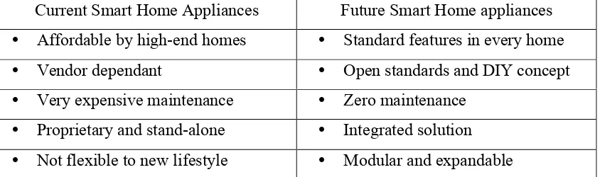
Table 1.1: Current and future smart home.
Current Smart Home Appliances Future Smart Home appliances • Affordable by high-end homes • Standard features in every home • Vendor dependant • Open standards and DIY concept • Very expensive maintenance • Zero maintenance
• Proprietary and stand-alone • Integrated solution • Not flexible to new lifestyle • Modular and expandable
1.4 Scope
This project is subjected to several scope and limitations that are narrowed down to the study. There are few scopes and guidelines listed to unsure the project is conducted within its intended boundary. This is to ensure the project is heading in the right direction to achieve its intended objectives. The scopes of this project are divided into two parts:
Hardware:
(a) PIC circuit that is used to store programs and to control the process of
sending message and also to connect the phone and the PIC circuit.
(b) Phone that is used to send SMS
(c) Circuit Driver as a connector for controlling switches from DC to AC 240V.
Software:
(a) PIC compiler to build program for PIC.
1.5 Summary of Methodology
4
set in the program. Next, the PIC will process the program and perform the tasks at the output that have been set in the program.
1.6 Report structure
This report of Home Appliances SMS Controller contains five chapters that explain detail about the project. The first chapter is the introduction of the project that included the objectives, scope, and problem statement of the project.
The second chapter is the literature review about the hardware and the software that will be used in this project and study of FBus Protocol for sending and receiving SMS.
The third chapter is about the methodology of the project and also PSM 1 and PSM 2 flowcharts.
Chapter four consist of the result and application of Home Appliances SMS Controller. It includes the circuit designing and development and also the simulation.
5
CHAPTER II
LITERATURE REVIEW
This chapter is discussing about the hardware and the software that will be using in the project.
2.1 Research Projects
2.1.1 Design and Development of Activation and Monitoring of Home
Automation System via SMS through Microcontroller
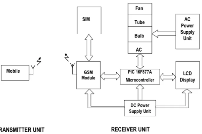
Home appliance control system based on GSM network technology for transmission of SMS from sender to receiver. SMS sending and receiving is used for universal access of appliances and allowing breach control at home. Appliance control subsystem enables the user to control home appliances remotely. The system is capable enough to give feed back to user about the condition of the home appliance according to the user’s needs and requirements. The home appliance control system consists of the following components [1]: -
6
Figure 2.1: Diagram of Home Appliances Control System.
Microcontroller: Microcontroller being the main module it control the appliances
system. This systems work on GSM technology for transmission from sender to receiver.
GSM Module: GSM module is a plug and play device and is attached to the
Microcontroller, which then communicates with the Microcontroller via port. GSM module is a medium to understand and encode the SMS receives or sends.
Cell Phone: Device to communicate with the GSM. Cell phone has a SIM card and a
GSM subscription. User transmits instructions via SMS and the system takes action against those instructions.
The different on the journal project and the home appliances project is that, it uses a GSM module to control the home appliances and the GSM module used an AT command to communicate with the microcontroller.
7
2.1.2 A MOBILE-BASED HOME AUTOMATION SYSTEM
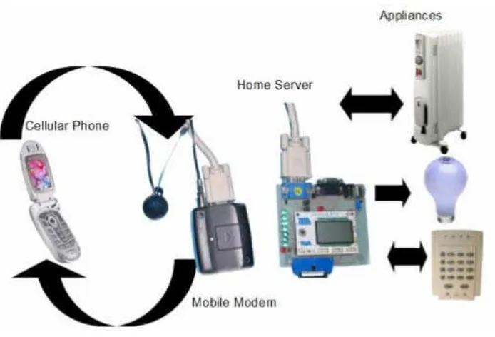
The journal is focusing on the mobile-based remote control system for controlling and monitoring of machine and devices at any time from anywhere within the coverage of cellular mobile networks. Home automation allows the controlling and monitoring of various home appliances by a single system.
[image:23.595.150.497.420.656.2]The mobile-based home automation system is shown in Figure 2.2. The system consists of a Java-enabled mobile phone, a cellular modem, and a controller board incorporating a microcontroller. The mobile phone serves as a remote control through which a user can interact with the home automation system. User- friendly graphical user interface is provided on the mobile phone through applications developed in Java programming language. The controller board resides at home and works as a home server, which carries out the task of operating and monitoring home appliances. The home server communicates with the remote control via the cellular modem [2].
Figure 2.2: Overview of a mobile-based home automation system.
8
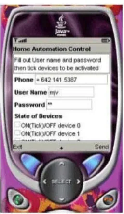
[image:24.595.256.385.213.434.2]then sent to the home server via SMS. The interface allows a user to specify phone number of the cellular modem, user name, password, and the state (on or off) that each home appliance should be set to. When the “send” button is pressed, all the data is put into a text string and sent via SMS to the cellular modem. On the reverse, feedback from the home server can be sent via the cellular modem to the mobile phone using SMS [2].
Figure 2.3: Cellular phone emulator running Java application.
The home server design is based on a microcontroller, an Atmel Butterfly. The requirements for the microcontroller are: a RS232 serial port, I/O (input/output), and a reasonable speed. In addition a reasonable amount of EEPROM is needed to store the home server software, appliance status, user name, and password [2].
From the journal, the system used a mobile modem for the connection between mobile phone to control the appliances. It also used java interface so that the interface can be user-friendly and easy to use. The microcontroller used is Atmel Butterfly.