HUMANOID ROBOT DEVELOPMENT
UMMUL AZKI BINTI MUSA
This report is submitted in partial fulfillment of the requirements for the award of Bachelor of Electronic Engineering (Computer Engineering) With Honours.
Faculty of Electronic and Computer Engineering Universiti Teknikal Malaysia Melaka
UNIVERSTI TEKNIKAL MALAYSIA MELAKA
FAKULTI KEJURUTERAAN ELEKTRONIK DAN KEJURUTERAAN KOMPUTER
BORANG PENGESAHAN STATUS LAPORAN PROJEK SARJANA MUDA II
Tajuk Projek : HUMANOID ROBOTIC DEVELOPMENT
Sesi Pengajian : 2008 / 2009
Saya UMMUL AZKI BINTI MUSA
mengaku membenarkan Laporan Projek Sarjana Muda ini disimpan di Perpustakaan dengan syarat-syarat kegunaan seperti berikut:
1. Laporan adalah hakmilik Universiti Teknikal Malaysia Melaka.
2. Perpustakaan dibenarkan membuat salinan untuk tujuan pengajian sahaja.
3. Perpustakaan dibenarkan membuat salinan laporan ini sebagai bahan pertukaran antara institusi pengajian tinggi.
4. Sila tandakan ( √ ) :
SULIT*
(Mengandungi maklumat yang berdarjah keselamatan atau kepentingan Malaysia seperti yang termaktub di dalam AKTA RAHSIA RASMI 1972)
(Mengandungi maklumat terhad yang telah ditentukan oleh organisasi/badan di mana penyelidikan dijalankan) TERHAD*
TIDAK TERHAD
Disahkan oleh:
__________________________ ___________________________________
(TANDATANGAN PENULIS) (COP DAN TANDATANGAN PENYELIA)
Alamat Tetap:
No 32, Jalan Canggung 13, Taman Pasir Puteh,
81700 Pasir Gudang.
Johor.
“I hereby declare that this report is the result of my own effort except for quote that have been cited clearly in the references.”
Signature : ……….. Student : UMMUL AZKI BINTI MUSA
“I hereby declare that I have read this report and in my opinion this report is sufficient in terms of the scope and quality for the award the Bachelor of Electronic Engineering
(Computer Engineering) With Honours”.
Signature : ... Name : EN. SANI IRWAN BIN MD. SALIM
DEDICATION
ACKNOWLEGMENT
ABSTRACT
ABSTRAK
TABLE OF CONTENT
CHAPTER TOPICS PAGES
PROJECT TITLE i
VERIFICATION STATUS OF REPORT ii
DECLARATION iii
VERIFICATION BY SUPERVISOR iv
DEDICATION v
ACKNOWLEDGMENT vi
ABSTRACT vii
ABSTRAK viii
TABLE OF CONTENT ix
LIST OF FIGURE xii
LIST OF TABLE xv
I INTRODUCTION 1.1 Introduction of Project 1
1.2 Objective 2
1.3 Problem Statement 2
1.4 Scope of Project 3
II LITERATURE REVIEW
2.1 Introduction 5
2.2 The Honda Humanoid 6
2.3 Preamble 7
2.4 Human Characteristics 9
2.5 Design Specifications 10
III METHODOLOGY 3.1 Introduction 13
3.2 Methodology 14
3.3 Gait Analysis 16
3.4 The Kinematics 17
3.5 Kinetics 17
3.6 Hardware 18
3.6.1 Lego 18
3.6.2 RCX 19
3.6.3 IR 20
3.6.4 Gear 20
3.6.5 Sensor 21
3.6.6 Motor 23
3.7 Software
IV RESULTS AND DISCUSSION
4.1 Introduction 25
4.2 Base Construction 25
4.3 Legs Construction 28
4.4 Body Construction 32
4.5 Combining Part 34
4.6 Software Implementation 39 4.6.1 Code Programming 39
4.7 Discussion 43
4.7.1 Movement of the Robot 43
4.7.2 Programming of the Robot 44
V CONCLUSION AND SUGGESTION
5.1 Conclusion 46
5.2 Suggestion 47
REFERENCES 48
APPENDIX 49
LIST OF FIGURES
NO. TITLE PAGES
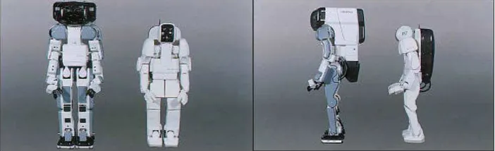
2.1 Front and Side view of P2 and P3 6
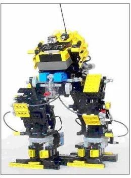
2.2 Preamble robot 8
2.3 Rotation sensors 9
2.4 Bipedal locomotion and humanoid robots. 9
3.1 Flow chart of create robot 14
3.2 Draft of the robot 15
3.3 A sample sequence of the silhouette of a walking 16
3.4 Lego’s Logo 18
3.5 The RCX Controller 19
3.6 IR Tower 20
3.7 Gears 20
3.8 Touch Sensor 22
3.9 Light Sensor 22
4.1 One of the robot’s legs (motor and gears usage) 26 4.2 Robot’s legs (motor and gears usage) 27
4.3 Firm the connection 27
NO. TITLE PAGES
4.5 The view of the robot’s legs 29
4.6 The right view of robot’s legs 29
4.7 The left view of robot’s legs 30
4.8 The gear usage 31
4.9 The ratio of gear 31
4.10 Part of robot’s body 32
4.11 The Bevel gear Usage 33
4.12 The Crown and 8-Teeth gear 33
4.13 Robot with body part 34
4.14 The front view of robot 35
4.15 The side view of robot 36
4.16 The completed robot 37
4.17 The front view of completed robot 38
4.18 Compiling process 39
4.19 Program with error 40
LIST OF TABLE
NO. TITLE PAGES
LIST OF ABBREVIATIONS
NQC - Not Quite C
CHAPTER I
INTRODUCTION OF PROJECT
1.1 Introduction
Robot is a machine whose behavior can be programmed. Basically, robots have five fundamental components such as a brain to controls the robot’s action and respond to sensory input, a robot’s body is simply the physical chassis that hold the other pieces of the robot together, actuators (motor) to allow the robot to move, sensors to give a robot information about its environment and a power source supplies to run the brain, actuators and sensors.
called the RCX (Robotic Command Explorer). It has three input ports, three output ports, four push-buttons and an infrared (IR) serial communication interface. The robot is using sensors and motors as detector and for the robot’s movement. The movement of the robot will be control by the LEGO Mindstroms bricks. The programming language that will be used is Not Quite C (NQC).
1.2 Objectives
1) Design and develop humanoid robotic system using LEGO mindstorms. 2) To develop a model of human movement, structure to mimic walking
movement.
3) To utilize sensors and motors that act as human joint to performs the movement.
1.3 Problems Statements
1) Most of the robot not stable enough, it will fall easily when it make a movement. It because the robot have no balancing (Dynamic systems).
1.4 Scope of Project
1) Using 3 brick LEGO MindStorms to create the humanoid robot that could stand and walk.
2) It uses RCX brick as a controller or robot’s brain.
3) The robot also uses a sensor to measures some attribute like position, orientation, speed and surrounding environment.
4) DC motors is used for motion in the robot such as muscles and joints.
1.5 Report Structures
1.5.1 Chapter 1
Chapter 1 provides a plan for the creation of the LEGO Humanoid Robot. It does this by listing the objectives, problem statement, scope, and the methodology of the project.
1.5.2 Chapter 2
Chapter 2 details how bipedal and humanoid robots have been develop in the past and what can be learnt from those efforts. Chapter 2 also provides background information on the human form including bone structure and how they combine within the human skeleton.
1.5.3 Chapter 3
1.5.4 Chapter 4
Chapter 4 details the result that obtained based on the methodology that used. The obtained result will be analyze and based on the objectives and problem statement.
1.5.5 Chapter 5
CHAPTER II
LITERATURE REVIEW
2.1 Introduction
This chapter deals with the work done by other researchers who have investigated about mechanical design of a humanoid. The concept behind the commencement of the program was to create a robot that could coexist and cooperate with human beings, by doing what a person cannot do and cultivating a new dimension immobility both of which would add value to society.
2.2 The Honda Humanoid
The Honda Humanoid Robot, The Honda Humanoid Robot, research began in
Figure 2.1: Front and Side view of P2 and P3. P3 is some 22 cm shorter and 80 kg lighter.
The engineers at Honda began their research on the .foot/leg walking mobile function; which corresponds to basic human mobility.
The studies that were conducted were:
1) Movement of leg/foot joints when walking 2) Joint alignment
3) Dimensions, weights and centre of gravity of each leg and foot 4) Torque application to the joints when walking
5) Sensor systems required for walking 6) Landing impact when walking
2.3 PREAMBLE
This robot is a single-RCX biped with the ability to turn within its own footprint. It's also first foray into doing a 'tough-looking' robot, as opposed to one that is purely functional.
Turning works by advancing the robot until the leg that leads the turn is in front (e.g., the right leg is forward for a right turn). To make a right turn, the robot takes its weight on the right foot (left leg off the ground) and turns the right ankle turntable about 15° to the right; it then takes half a step back onto the left foot, raising the right foot so that it can straighten the right ankle. It then moves its weight forward onto the right foot again, turns the ankle another 15°, and so on. This procedure can repeated until the robot has turned the desired amount. The advantage of turning in this way is that the robot turns pretty much within its own footprint, no requirement for maneuvering in large-diameter circles.
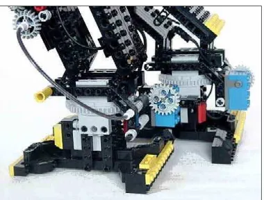
2.3.1 Mechanics
The lower (belly) motor drives a worm-24t gearbox. The axle from the 24t gear connects to two cams, one for each leg, offset 180°, lifting and moving the legs alternately to provide a walking action.
Figure 2.2: Preamble robot
Figure 2.3: Rotation sensors
Figure 2.4: There has been much research into bipedal locomotion and humanoid robots.