Hybrid Vibration Energy Harvester Based On
Piezoelectric and Electromagnetic Transduction
Mechanism
Mohd Fauzi. Ab Rahman
1, Swee Leong. Kok
2, Noraini. Mat Ali
3, Rostam Affendi. Hamzah
4, Khairul Azha. A.Aziz
5 1,4,5Faculty of Engineering Technology, 2,3Faculty of Electronic and Computer Engineering Universiti Teknikal Malaysia Melaka
Hang Tuah Jaya,76100 Durian Tunggal, Melaka, Malaysia
1
2
Abstract— Vibration energy harvester converts kinetic
energy from ambient vibration into electrical energy. Many energy harvesters in the literature use single element transducer, either piezoelectric, electromagnetic or electrostatic for above purpose. In this paper, a hybrid based energy harvester that integrates with both, piezoelectric and electromagnetic transducers is developed and examined. The energy harvester uses four pole magnets arranged onto a piezoelectric cantilever beam free end, to produce stronger magnetic field over a stationary coil. When the harvester is excited by an external vibration, both piezoelectric and electromagnetic generates electrical energy or power. Experimental results shows that piezoelectric capable to generate optimum power of 2.3mW in a 60kΩ resistive load, while electromagnetic generates 3.5mW power in a 40Ω resistive load, when vibrated at its resonant frequency 15Hz, and at 1g (1g=9.8ms-2) acceleration. By efficiently integrating both piezoelectric and electromagnetic transducers, more power could be generated as compared to a single transducer over its size.
Index Terms— Hybrid, vibration, energy harvester,
piezoelectric, electromagnetic.
I.INTRODUCTION
Vibration energy harvesting is receiving considerable amount of interest for the past decade. This is led by the growing potential of self powered devices, such as sensor node [1]. The sensor node is normally small in size, utilizes very low power, large in numbers, communicates wirelessly, and being located in a place where practically inaccessible for retrofit, has made the vibration energy harvester, desirably as an alternative solution for the inexhaustible power source. [2-6]
There are many vibration energy harvesters that have been demonstrated in the literature [4], however most of
them are using single element transducer such as piezoelectric, electromagnetic and electrostatic to convert kinetic energy from ambient vibrations into useful electrical energy. Among these harvesters, piezoelectric and electromagnetic are considerably popular over others, mainly due to its capability to generate greater power density. [4-5]
S. Beeby [3] developed a miniscale electromagnetic energy harvester prototype that consists of a coil and a silicon wafer cantilever beam, with four pole magnets as its proof mass. The harvester was able to produce considerably high power over its size. Meanwhile, earlier Roundy [5] developed a miniscale piezoelectric energy harvester that have a similar structure to what have been demonstrated by S. Beeby. The harvester is using piezoelectric instead of silicon wafer as the cantilever beam, and tungsten alloy as the proof mass instead of the magnets. In this paper, we integrate both piezoelectric and electromagnetic transducer in a hybrid unit to exploit more power without increasing much on its size. By using a piezoelectric cantilever beam and four pole magnets as the proof mass, and with a coil centrally placed in between of the magnets, an efficient hybrid vibration energy harvester is feasible to be made.
The purpose of this paper is to examine the feasibility of integrating both transducers, electromagnetic and piezoelectric as a hybrid harvester in order to generate more output power. The main focus here is on the harvester itself rather than on the associated power electronics.
II.BASICVIBRATIONENERGYHARVESTER MODEL
z
Fig. 1.Generic model illustration of linear vibration energy harvesters based on Single Degree Of Freedom (SDOF).
The damper comprises two ports; electrical and mechanical damping that represents the transduction mechanism. When the energy harvester is excited by ambient vibration source, the inertial mass, moves out of phase with the harvester’s housing. This effect eventually creates a relative displacement between the mass and the housing or mechanical stress.
As shown in Figure 1, x is the absolute displacement of the inertial mass, y is the displacement of the housing and z
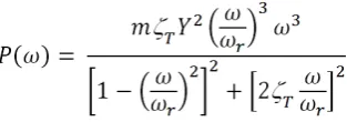
is the relative motion of the mass with respect to the housing. Electrical energy could be obtained from the transduction mechanism by exploiting either displacement or strain. According to Williams and Yates [7], total average power that capable to be generated from the harvester could be equated as,
(1) where ζT is the total damping, Y is the displacement of the
housing and ωris the resonant frequency.
A typical energy harvester has its own resonant frequency, and maximum output power is capable to be generated, when the resonant frequency of the harvester matches the ambient vibration frequency, and could be equated as,
(2)
(3) where a = Yω2
is the excitation acceleration. Equation 3 implies that output power of an energy harvester is proportional to its mass and excitation acceleration squared and inversely proportional to its resonant frequency and damping.
III.HYBRIDENERGYHARVESTER CONFIGURATION
A.Hybrid Energy Harvester Configuration
A centered brass reinforced piezoelectric cantilever purchased from Piezo Systems Inc. with dimension 63.5mm x 31.8 mm x 0.51mm was bolted securely on a shaker at one end. At the other end of the cantilever, four rectangular shaped Neodymium magnets with dimension of 25 mm x 10 mm x 5 mm were arranged at the tip of the cantilever to build a four magnetic poles with a gap in between to fit a magnetic coil at the center. as shown in Figure 2. The magnetic coil has 8 mm inner diameter and 13 mm outer diameter, and was made by winding up 1200 turns with 0.02sq mm BELDEN 8057 USA magnet wire. The coil, then was fixed to the desired location and height. A platform made from acrylic sheet was used to hold the coil rigidly to the centre of the cantilever-magnets structure.
When the harvester was excited by an external vibration, two things would happen; first, deformation experienced by the piezoelectric cantilever beam due to the oscillation, would result in strain or stress, that eventually converted into electrical energy, second, when the cantilever-magnets oscillates up- and down, it would produce considerably strong magnetic flux changes. This would induce an AC current in the stationary coil which would be measured as open circuit output voltage at the terminals of the coil. The output electrical power can be measured by inserting external load to the terminals of the coil.
Fig. 2.Cross section view through the four poles magnets arrangement.
B.Experiment Set-up
In this study, three different acceleration values; 0.1g, 0.5g and 1g levels with input vibration frequency of 15 Hz that matches the harvester resonant frequency were examined. These chosen acceleration values represents the acceleration levels generally presence in ambient vibrations. Typically cantilever based energy harvester would produces maximum output power when it is excited at its resonant frequency. The set-up of the experiment is as shown in Figure 3, which consists of the hybrid harvester; piezoelectric cantilever beam with the magnets that placed on a shaker and a fixed coil.
Fig. 3.Hybrid harvester voltage measurement
The desired frequency and acceleration level of the vibration source is set by tuning the function generator that feed into a power amplifier which excites the shaker. The acceleration level of the shaker is measured with ADXL 325 which was fixed and bolted securely on the shaker stage. In order to ensure correct reading was being taken, the input frequency from the function generator to the shaker was compared with the output of the piezoelectric cantilever measured with oscilloscope at a range of frequency beyond the resonant frequency.
Measurements of the output voltage from each transducer were carried out once the primarily setting was completed. In order to determine the harvester optimal output power, a series of resistive load using a decade resistance box is connected in parallel to the energy harvester. The output voltage for each of the energy harvester; piezoelectric and electromagnetic alike, is measured across the resistive load and the output power can be derived as P = V2/R.
C. Energy harvester circuit
POWER STORAGE
UNIT FIXED
END
PIEZOELECTRIC CANTILEVER BEAM
POWER OUTPUT
NEODYMIUM MAGNET
N S
S N
COIL
+
_
+
_
Fig. 4.Experiment device diagram
Hybrid energy harvester with the integration of piezoelectric and electromagnetic transducer in a system
requires two separate bridge rectifier as shown in Figure 4. This is to ensure that the electrical output generated from each of the transducer element would not be transferring backward to the other, which would reduce the total electrical output from the system.
In this study, we use two bridge rectifiers with each connected to either piezoelectric or electromagnetic transducer. When the harvester is excited by an external vibration, each transducer in the harvester system would generate an AC output voltage, which is then be rectified through the bridge rectifier from AC to DC voltage conversion. After the rectification take place, the DC voltage would be stored in the storage component, normally super capacitor or rechargeable battery for later use.
IV.RESULT
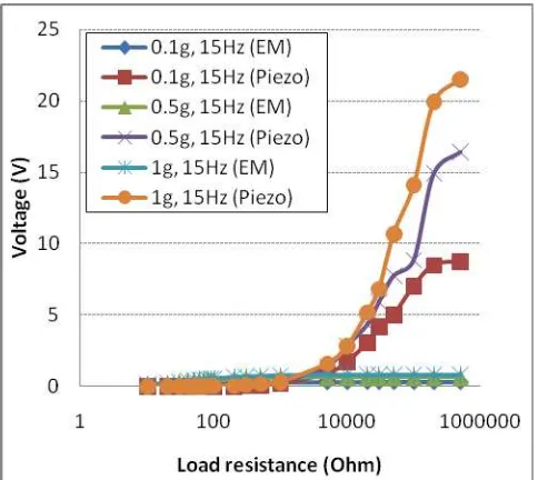
The measured output voltage at a range of resistive load from each of the energy harvester; piezoelectric and electromagnetic is shown in Figure 5. The harvester was excited at its resonant frequency 15 Hz, under three different accelerations, 0.1g, 0.5g and 1g. From the graph, it shows that in all cases, piezoelectric generates significantly high voltage compared to the electromagnetic when the load increases.
Fig. 5. Generated voltage in correlation with the load resistance
Fig. 6. Current in correlation with the load resistance
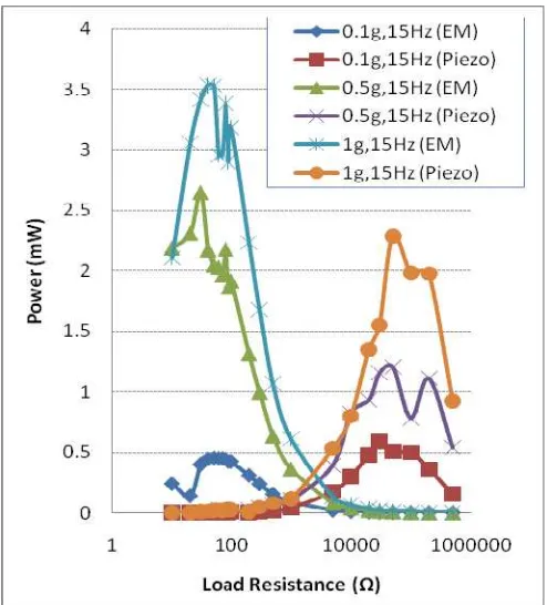
Fig. 7. Output power in correlation with load resistance
Figure 7 shows that when the harvester is vibrated at its resonant frequency of 15Hz, at three different level of acceleration 0.1g, 0.5g and 1g, a significant level of output power at different range of resistive load generated by each of the energy harvester can be clearly observed. Electromagnetic transducer generates optimum power when the load resistance is low, while piezoelectric generates optimum power when connected to a high resistance load. Electromagnetic transducer is capable of generating useful output power up to 0.45 mW (load equals 50 Ohm), 2.6 mW
(load equals 30 Ohm), and 3.5mW (load equals 40 Ohm) with respect to the acceleration level of 0.1g, 0.5g and 1g. Meanwhile for piezoelectric, optimal output power that could be generated is 0.59 mW (load equals 30 kOhm), 1.2 mW (load equals 50 kOhm), and 2.3mW (load equals 50 kOhm) when being excited at acceleration level of 0.1g, 0.5g and 1g respectively.
Based on the findings, when the harvester is exposed to vibration, it would generate electrical energy that could be kept for future use. By integrating these two transducers, more electrical energy could be generated as compared to single transducer.
Furthermore, incorporating the piezoelectric-four poles magnets cantilever beam to induce flux for electromagnetic transduction, capable of reducing the size of the hybrid harvester because the coil shares the same piezoelectric
cantilever beam, as compared to hybrid system that contains separately two cantilever beams; one for piezoelectric and the other for electromagnetic for transduction purpose.
By selecting piezoelectric extending type transducer as the cantilever beam for electromagnetic, the size of the harvester could be optimized, thus enabling both transduction activity, piezoelectric and electromagnetic to occur at the same time. Incorporating the four pole magnets as the proof mass of the cantilever beam, would create a greater flux gradient concentration inside the stationary coil, hence would also generating more output power when external resistive load is connected.
V.CONCLUSION
A hybrid vibration energy harvester, integration of piezoelectric and electromagnetic transduction mechanism was designed and tested. The harvester consists of piezoelectric cantilever beam with four magnets fixed and arranged at its end, leaving a gap between the magnets for a coil placement area. When a vibration source is applied to the energy harvesting system, the piezoelectric beam and the magnets would oscillate as one unit, produces a stress/strain in the piezoelectric and a change of magnetic flux in the coil, which result in generation of useful electrical power from both transducers. The harvester is capable of producing useful power of 3.5 mW (30 Ω load) from electromagnetic transducer, and 2.2mW (50 kΩ) from piezoelectric transducer. These powers are generated when the harvester is tested at exciting vibration frequency, 15 Hz and at 1 g acceleration level.
VI.ACKNOWLEDGMENT
VII.REFERENCES
[1] S. Yingjun, H. Xueliang, L. Hexiang, and J. Ping, "A Vibration-Based Hybrid Energy Harvester for Wireless Sensor Systems," Magnetics, IEEE Transactions on, vol. 48, pp. 4495-4498, 2012.
[2] M. F. Bin Ab Rahman and K. Swee Leong,
"Investigation of useful ambient vibration sources for the application of energy harvesting," in Research and Development (SCOReD), 2011 IEEE Student Conference on, 2011, pp. 391-396.
[3] S. P. Beeby, R. N. Torah, M. J. Tudor, P. Glynne-Jones, T. O. Donnell, C. R. Saha, and S. Roy, "A micro electromagnetic generator for vibration energy
harvesting," Journal of Micromechanics and
Microengineering, vol. 17, p. 1257, 2007.
[4] P. D. Mitcheson, E. M. Yeatman, G. K. Rao, A. S. Holmes, and T. C. Green, "Energy Harvesting From
Human and Machine Motion for Wireless Electronic Devices," Proceedings of the IEEE, vol. 96, pp. 1457-1486, 2008.
[5] S. Roundy, P. K. Wright, and J. Rabaey, "A study of low level vibrations as a power source for wireless sensor nodes," Computer Communications, vol. 26, pp. 1131-1144, 2003.
[6] R. Torah, P. Glynne-Jones, M. Tudor, T. O. Donnell, S. Roy, and S. Beeby, "Self-powered autonomous wireless sensor node using vibration energy harvesting,"
Measurement Science and Technology, vol. 19, p. 125202, 2008.