UNIVERSITI TEKNIKAL MALAYSIA MELAKA
DEVELOPMENT OF NAVIGATION SYSTEM FOR
AUTONOMOUS MOBILE DEVICE
This report submitted in accordance with requirement of the Universiti Teknikal Malaysia Melaka (UTeM) for the Bachelor Degree of Manufacturing Engineering
(Robotic and Automation) with Honours.
by
LUQMAN HAKIM BIN KASMON
ii
DECLARATION
I hereby declare that this report entitled Development of Navigation System for Autonomous Mobile Device is the result of my own research except as cited in the
references.
Signature :
iii
APPROVAL
This report is submitted to the Faculty of Manufacturing Engineering of UTeM as a
partial fulfillment of the requirements for the degree of Bachelor of Manufacturing
Engineering (Robotic and Automation). The members of the supervisory committee
are as follow:
iv
ABSTRACT
An Autonomous Mobile Device (AMD) has ability to choose alternatives pathways
if any obstacles exist in its pathways in order to achieve its goal. This project aim to
develop a navigation system for AMD during scanning process of the pathways is
completed by using three sonar sensors. The data of the scanning will be sent to
Personal Computer by using Bluetooth module. Then, HyperTerminal will display
v
ABSTRAK
Alat Mudah Alih Automatik (AMD) boleh memilih jalan alternatif sekiranya wujud
halangan di atas jalannya dalam usaha untuk mencapai matlamatnya. Projek in yang
bertajuk Pembangunan Sistem Navigasi untuk Alat Mudah Alih Automatik selepas
proses peninjauan mengunakan tiga penderia sonar. Data-data peninjauan akan
dihantar ke Komputer Peribadi menggunakan modul Bluetooth. Kemudian
HyperTerminal akan memaparkan data-data selepas data diproses oleh
vi
ACKNOWLEDGEMENTS
All Praise to Allah, the Lord of the Worlds, and prayers and peace be upon
Muhammad Rasulullah S.A.W, His servant and Messenger. Alhamdulillah, with
Allah blessings and guidance, I have completed this project successfully even though
along the way, there are many hardship and obstacles.
First of all, I would like to acknowledge the inspiring professionalism and
dedicated which support of my thesis supervisor, Pn.Silah Hayati binti Kamsani. Her
constant guidance and support during my thesis writing is invaluable to me and
continuous direction and opinion regarding the flow of the project has an invaluable
contribution to achieve the objectives of the project.
Thanks to Mr. Shariman bin. Abdullah for help me in programming the
microcontroller that integrates with sonar sensors and DC motor. A lot of appreciate
to him because willing to spend time, sharing experience, ideas, guidance and
opinion to accomplishing this project especially in programming field.
Last but not least, I thank everyone who involved directly and indirectly in
this project. The sacrifice and commitment given towards me earning my Bachelor’s
Degree are indescribable and without them, this PSM thesis would have been good
vii 2.2.1. Peripheral Interface Controller (PIC) 16
2.2.1.1. PIC16F877 20 2.2.2. Atmel 20
2.2.3. Motorola 21 2.2.4. Comparison of Microcontroller 22 2.3.Language of PIC 23
viii
2.4.1.3. Servo Motor 33
2.4.1.4. Stepper motor 34
2.5.Application of Sensor in Autonomous Mobile Device 35
2.5.1. Sonar 35
2.6.3. Infrared Data Association (IrDA) 55
2.7.Mapping Concept 57
2.7.1. Metric path planning, 58
2.7.2. Configuration Space 59
2.7.3. Cspace Representations 59
2.7.3.1. Regular grids 60
2.7.3.2. Wavefront Based Planners 60
2.8.Summary of Literature Review 62
3.0 METHODOLOGY 63
3.1.Problem Statement 65 3.2.Strategic Planning 65
3.3.Research about Project 67
3.3.1. Assembling the Mobile Robot 67
3.3.1.1. Assembling the Electronic Components 68
3.3.1.2. Programming PIC microcontroller 69
3.3.2. Simple Movement 70
3.3.3. Bluetooth Module Programming and Testing 71
3.4.Combination of Autonomous Mobile Robot 71
3.5.Scanning the Path 72
3.6.Navigation System 73
3.7.Improvement/Modification 74
ix
4.0 DESIGN AND DEVELOPMENT 75
4.1Main controller board 75 4.2 Initial development of AMD 82 4.3 DC Motor Control Motion 83
4.4 Ultrasonic Range Finder 84 4.5 Serial communication 86 4.6 Navigation system 88
4.7 Final development of AMD 90
5.0 RESULT AND DISCUSSION 94 5.1. Experiment with Ultrasonic Range Finder 94 5.1.1. Condition testing 94 5.1.2. Serial communication testing 96 5.1.3. Data transmission from Ultrasonic Range Finder 98 5.1.4. Bluetooth communication 99 5.1.5. Obstacle Avoidance 101
5.2. Overall Discussion 102
6.0 CONCLUSION AND SUGGESTION FOR FURTHER WORK S 104
6.1.Conclusion 104
6.2.Suggestion for future works 104
REFERENCES 106
x
LIST OF FIGURES
2.1 Auto assembly plant-spot welding robot of KUKA 5
2.2 Mars robot Sojourner, USA 5
2.3 Façade-cleaning robot, Comatec, France 6
2.4 Trilobite from Electrolux 6
2.5 Design of an ideal differentially driven robot 7
2.6 Basic design of track-driven robot 8
2.7 Depiction of basic navigation 9
2.8 Three strategies for getting to a destination 10
2.9 Perceiving the environment 12
2.10 Ultrasound sensor with safety license (upper); 2-D laser scanner 13 (middle) and CCD camera (lower).
2.11 Ultrasound scan of standing paper rolls 13
2.12 Environmental modeling 14
2.13 Functional diagram for determining pose of vehicle 15
2.14 Cleaning path based on a linear environmental model 16
2.15 Components of typical full-featured microcontroller 17
2.16 PIC16F887 PDIP 40 Microcontroller 20
2.17 40 Pin AT90S8535 21
2.18 48-Pin DIP pin assignments of MC68HC11 22
2.19 A typical actuating unit 27
2.20 Configuration classification of electric motors 28
2.21 Motor construction and terminology 29
2.22 Cross sectional of DC spur gear motor 30
2.23 Brush-type iron core armature permanent magnet DC motor assembly 31
2.24 AC induction motor components and assembly view 32
2.25 RC servo motor 33
2.26 Wires of servo motor 34
xi
2.28 Unipolar and Bipolar Stepper Motor Windings 36
2.29 Stepper motor movement 36
2.30 Stepper Motor Torque Speed Curve 37
2.31 Ultrasonic Range Finder 39
2.32 Sonar sensor structure 39
2.33 TOF principleof sonar sensor 40
2.34 The regions of space observed by an ultrasonic sensor 40
2.35 2D mapping using sonar sensor 43
2.36 Maps produced by a mobile robot using sonar 44
2.37 PIR (Passive Infra-Red) Sensor 44
2.38 The object deactivates the receiver 45
2.39 The object activates the receiver 45
2.40 Sick LMS 200 scanner and the TOF ranging principle 47
2.41 Mapping using 2D laser range finder 47
2.42 Commercially available CCD chips and CCD cameras 49
2.43 Bluetooth Chip 52
2.44 Zigbee Topology 54
2.45 Reduction of a 6DOF world space to a 2DOF configuration space 59
2.46 Regular grid 60
2.47 A wave propagating through a regular grid‘ 61
3.1 Methodology of project 64
3.2 Gantt chart 66
3.3 DC Gear Motor Mobile Robot Base Set 68
3.4 The Flowchart of Programming for PIC microcontroller 69
3.5 Flowchart of simple movement 70
3.6 Flowchart of Bluetooth Communication 71
3.7 AMD orientations 72
3.8 Flowchart of scanning path 73
xii
4.1 SK40B PIC Microcontroller Start-Up Kit 76
4.2 SK40B PIC Microcontroller Start-Up Kit schematic diagram 77
4.3 The main controller board circuit 79
4.4 DC gear motor power distributor 80
4.5 The process development of board circuit 80
4.6 First development of main controller board 81
4.7 Second development of main controller board 81
4.8 The right placement of Zener diode in circuit 81
4.9 Connection of pin RX and TX of PIC16F877A for serial communication 82
4.10 The initial development of AMD 83
4.11 Motor Driver 83
4.12 Voltage regulator circuit and PIC microcontroller 83
4.13 Battery and power distributor 83
4.14 Basic connection Ultrasonic sensor to PIC16F877A 85
4.15 LV MAXSonar EZ-1 schematic diagram 86
4.16 Source code of DC motors and limit switches 87
4.17 UC00A USB to UART converter 88
4.18 KC Wirefree Bluetooth Module Starter Kit SKKCA-21 88
4.19 The source code to display the value data from sonar sensor 89
4.20 Calculation value data from sonar sensor 89
4.21 The source code navigation system for center sonar sensor. 90
4.22 The layout of navigation for AMD 90
4.23 The goal of navigation 90
4.24 Top view of AMD 91
5.1. The analog voltage from sensor 94
5.2. The probe reading by multimeter at sonar sensor pins 95
xiii
5.4. Serial communication testing on HyperTerminal 96
5.5. Simulation of serial communication testing 97
5.6. HyperTerminal Setting 97
5.7. Serial communication testing on HyperTerminal 97
5.8. Depiction for data transmission way from unknown environment 98
5.9. The display of data from sonar sensor on HyperTerminal 98
5.10. Graph of data transmission from sensor 99
5.11. COM Properties dialogue box 100
5.12. The serial communication from sonar sensors to HyperTerminal 100
5.13. The result from serial communication from three sonar sensor by using
Bluetooth module. 99
xiv
LIST OF TABLES
2.1. Comparison of the possible strategies 11
2.2. Comparison between Microcontroller and Personal Computer 18
2.3. Comparison of characteristics of microcontrollers 22
2.4. Advantages and disadvantages of DC motor 30
2.5. Advantages and disadvantages of AC motor 32
2.6. Advantages and disadvantages of servo motor 34
2.7. Advantages and disadvantages of stepper motor 37
2.8. Comparison between sensors and transducers 38
2.9. The advantages and disadvantages sonar sensor 42
2.10. Advantages and disadvantages of laser range finder 48
2.11. Similarity and Dissimilarities between Metric Path Planning 62
(Metric Navigation) and Topological Navigation
3.1 List of electronics and tools components 68
4.1 SK40B Information 76
4.2 Concept of wheel movement direction 84
xv
AMD - Autonomous Mobile Device
AMR - Autonomous Mobile Robot
BASIC - Beginner`s All-purpose Symbolic Instruction Coding
CCD - Charged Coupled Device
CLH - Cluster Head
CMOS - Complementary Metal Oxide Semiconductor
DC
SONAR - SOund NAvigation and Ranging
TOF - Time of Flight
VB - Visual Basic
1
CHAPTER 1
INTRODUCTION
2
cope with various uncertainties to complete the tasks. These uncertainties arise from various reasons; knowledge about the environment is partial and approximate; environmental changes are dynamical and can be only partially predicted, the robot’s sensors are imperfect and noisy; and the robot’s control is imprecise (Kaplan, 2006).
1.1. Problem Statement
3 1.2. Objectives
Due to the problem statement that had been stated before, below is the objectives that need to be achieved.
(i) To integrate the PIC programming and electronic components to develop a navigation system for an autonomous mobile device by using sonar sensor and will send sonar data to PC through Bluetooth module.
1.3. Scope
The scope of this project is to develop a navigation system for autonomous mobile device where the on-board sonar sensor will scan the path first in front on it, for any obstacle before continuing its journey. Thus, in a predetermined area, this device shall be able to locate any obstacle within the area and this information will be transmitted to PC by using Bluetooth module on-board the device. Other the scopes of this project are described as below.
(i) This autonomous mobile device shall not be developed but shall be assembled from the existing mobile robot kit available commercially in the market.
(ii) Peripheral Interface Controller (PIC) microcontroller will be for mobility purposes so that the device can move to the right, left, reverse and forward. PIC also will involve in sonar data programming and Bluetooth communication between AMD and personal computer.
4
CHAPTER 2
LITERATURE REVIEW
This chapter will present the literature reviews relevant to this project. It includes microcontroller, language of the microcontroller programming, sensor, motor, communication and wireless, and interfacing between computer and autonomous mobile robot, and mapping and algorithm concept. At the end of this chapter, the selection of type of microcontroller, language of the microcontroller programming, sensor, motor, interfacing of software, and mapping algorithm was made after comparison had been done among them.
2.1 Autonomous Mobile Device
5
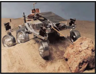
explore and to carry out geological measurement of Mars in summer 1997. It was almost completely teleoperated from Earth.
Figure 2.1: Auto assembly plant-spot welding robot of KUKA (Siegwart and Nourbakhsh 2004)
Figure 2.2: Mars robot Sojourner, USA (Murphy 2000).
6
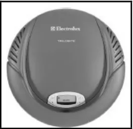
vacuum floor cleaning. The small size of Trilobite enables it to pass under tables and reach into tiny corner and navigate around the expensive vase to do a cleaning job (Lewis and Ge, 2006).
Figure 2.3: Façade-cleaning robot, Comatec, France (Schraft and Schmierer 2000).
Figure 2.4: Trilobite from Electrolux (Lewis and Ge 2006).
7
machines that are expected to operate in partially unknown and unpredictable environments. In addition, Velagic et al. (2006) mentions the basic feature of an autonomous mobile robot is its capability to operate independently in unknown or partially known environments.
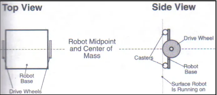
AMD have a large variety of possible ways to move. Thus, needs locomotion mechanisms that enable it to move unbounded throughout its environment. The locomotion of AMD or mobile robot are comprised into three types; wheels, legs and tracks as defined by McComb and Predko. Wheels are the most well-liked method for AMD to move. Wheels can be just about any size, limited only by the dimension of the robot. The numbers of wheels that commonly use is two which create a differentially driven robot as shown in Figure 2.5. In this case, the AMD or robot specifically is balanced on the two wheels by one or two free-rolling castors. There are also more powerful four- and six-wheel differentially driven robot have also been built which all the wheels on a side together provide the robot with better stability and traction than just two wheels.
Figure 2.5: Design of an ideal differentially driven robot (McComb and Predko 2006).
8
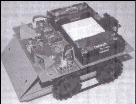
Meanwhile, the basic design of track-driven robots as shown in Figure 2.6 is pretty simple and is based on the differentially driven principle used with wheeled robots. Two tracks, one on each side of the robot, act as giant wheels. The tracks turn, like wheels, and the robot lurches forward or backward. For maximum traction, each track is about as long as the robot itself.
Track drive as shown in Figure 2.6 is preferable for many reasons, including the fact that it makes it possible to mow through all sorts of obstacle, like rocks, ditches, and potholes. Given the right track material, track drive provides excellent traction, even on slippery surfaces like snow, the concrete, or a clean kitchen floor. Track-based can be challenging to design and build, but with the proper track material along with powerful motors they are an excellent base for robots and offer the advantages of two wheeled differentially driven robots with greater stability and ability to transverse uneven terrain.
Figure 2.6: Basic design of track-driven robot (McComb and Predko 2006).