THE EFFECTS OF ICE FORMATION ON AIRFOIL PERFORMANCE
MOHD AZARUL SYAZARI BIN CHE AZIZ
NAME : MOHD AZARUL SYAZARI BIN CHE AZIZ
MATRIX NO . : B040910167
COURSE : Bachelor of Mechanical Engineering (Thermal Fluids)
SUPERVISOR : MISS NUR HAZWANI BINTI MOKHTAR
EVALUATOR : MR. MOHD SHUKRI BIN ZAKARIA
I
SUPERVISOR DECLARATION
“I hereby declare that I have read this thesis and in my opinion this report is
sufficient in terms of scope and quality for the award of the degree of Bachelor
of Mechanical Engineering (Thermal Fluids)”
Signature : ...
Supervisor : Miss Nur Hazwani binti Mokhtar
II
DECLARATION
“I hereby declare that the work in this report is my own except for summaries
and quotations which have been duly acknowledged.”
Signature: ...
Author: Mohd Azarul Syazari bin Che Aziz
III
IV
ACKNOWLEDGEMENT
I would like to express my utmost appreciation to Miss Nur Hazwani binti Mokhtar, my main supervisor for her guidance, cooperation and support throughout this project.
Special thanks also for my fellow project mates whom had given assistance in completing this project.
V
ABSTRACT
VI
ABSTRAK
VII
TABLE OF CONTENTS
CHAPTER TITLE PAGE
SUPERVISOR DECLARATION i
DECLARATION ii
DEDICATION iii
ACKNOWLEDGEMENT iv
ABSTRACT v
TABLE OF CONTENTS vii
LIST OF TABLES x
LIST OF FIGURES xi
LIST OF SYMBOLS xiv
LIST OF APPENDICES xv
CHAPTER 1 INTRODUCTION
1.0 Introduction 1
2.0 Problem Statement 2
VIII
2.2.1 Aircraft Cruising Altitudes 9 2.2.2 Significance of Experimental Data 9
2.2.3 Airfoil Ice Formation 11
Documentation
2.3 Computational Fluid Dynamics (CFD) Overview
2.3.1 Grid Generation 15
2.3.2 Turbulence Modelling 17
CHAPTER 3 METHODOLOGY
3.1 Introduction 18
3.2 Modelling 21
3.3 Grid Dependence Study 22
3.4 Boundary Conditions and Turbulence Models 23
3.5 Validation 24
CHAPTER 4 RESULT AND ANALYSIS
4.1 Introduction 25
IX
CHAPTER 5 CONCLUSION
5.1 Conclusion 38
5.2 Recommendations 39
REFERENCES 40
X
LIST OF TABLES
NO. TITLE PAGE
2.1 Selected Aircraft Specification 11
2.2 GLC305 airfoil coordinates 13
3.1 Number of nodes and elements 24
XI
LIST OF FIGURES
NO. TITLE PAGE
2.1 Rime ice (left) and glaze ice (right) formation 5
2.2 Aircraft with ice formation on land 6
2.3 Pneumatic De-icing Boot 8
2.4 Overall Dimensions of GLC305 airfoil 12
2.5 GLC305 airfoil shape 14
2.6 GLC305 airfoil with rime ice formation 14
2.7 GLC305 airfoil with glaze ice formation 15
2.8 Inner grid and Outer grid of single block grids 16
3.1 Flowchart of Study 20
3.2 Clean GLC305 airfoil from SOLIDWORKS 21
3.3 GLC305 airfoil with rime ice from SOLIDWORKS 21 3.4 GLC305 airfoil with glaze ice from SOLIDWORKS 22
XII
3.6 Close up view of C-Mesh 23
3.7 Mesh Dependency Study 24
3.8 Graph of Coefficient of Lift versus Angle of Attacks 27 for Clean Airfoil
4.1 Graph of CL versus angle of attacks for all airfoil 29 configurations
4.2 Pressure distribution of clean airfoil at 12 degree 30 angle of attack
4.3 Pressure distribution of rime ice airfoil at 12 degree 31 angle of attack
4.4 Pressure distribution of glaze ice airfoil at 12 degree 31 angle of attack
4.5 Velocity distribution of glaze ice airfoil at 6 degree 31 angle of attack (30,000 feet)
4.6 Velocity distribution of glaze ice airfoil at 12 degree 32 angle of attack (30,000 feet)
4.7 Airflow vector of rime ice at 12 degree angle of 32 attack (30,000 feet)
4.8 CL versus Angle f Attacks at Different Altitudes for all 34 airfoil models
XIII
LIST OF SYMBOLS
CD = Coefficient of Drag CL = Coefficient of Lift Re = Reynolds Number U = Relative velocity V = Viscosity of air
L = Length
XIV
LIST OF APPENDICES
NO. TITLE PAGE
A Result of Validation Simulation 44
B Average Percentage of Error 44
C Table of CL at specific angle of attacks for all airfoil 45 configurations
D Table of CL for clean airfoil at specific angle of 45 attacks for three altitudes
E Table of CL for rime ice airfoil at specific angle of 46 attacks for three altitudes
F Table of CD for rime ice airfoil at specific angle of 47 attacks for three altitudes
G Table of CL for glaze ice airfoil at specific angle of 48 attacks for three altitudes
XV
attacks for three altitudes
I Pressure distribution contour for Glaze Ice 49
J Meshing 50
1
CHAPTER 1
INTRODUCTION
1.0 INTRODUCTION
2
states that the accuracy of the simulation depends on the grid quality and also turbulence model that were used in order to reproduce all flow characteristics that are needed.
Previous studies had shown several significant findings that are very important for flight safety. Based on simulation by Chi et al (2005) using CFD software, stall angle had drop for as much as 30% when ice formation was formed on the airfoil. Hence, the objective of this study is to simulate and analyze the airflow around a 2D airfoil with and without ice formation on the leading edge. In this study, the result will further elaborated from previous studies because there will also be analysis on airfoil performance due to change of altitudes.
1.1 PROBLEM STATEMENT
Past aviation history had seen numerous flight accidents due to ice formation on the aircraft body, particularly the airfoil. When ice was formed on the airfoil surface, the integrity of the overall shape of the airfoil will be disturbed. This is because the flow around the airfoil will not be as desired, resulting in loss of performance of the airfoil itself. Such airfoil characteristics that will be disturbed are the lift coefficient, drag coefficient and also pitching moment coefficient. Hence, further study needs to be done in order to understand the characteristics of ice formation on airfoil performance.
3
1.2 OBJECTIVE
The objectives of this study are to simulate and analyze the airflow around 2D airfoil with and without ice formation on the leading edge.
1.3 SCOPE OF STUDY
There are three scopes of this study which are:-
a) Construct three types of airfoil models which are clean airfoil, airfoil with rime ice shape and airfoil with glaze ice shape.
b) Simulate the airflow around the three models using CFD.
4
CHAPTER 2
LITERATURE REVIEW
2.0 LITERATURE REVIEW
The terms ‘ice formation’ and ‘airfoil performance’ are the two main priorities of this
5
2.1 ICE FORMATION
2.1.1 TYPES OF ICE FORMATION
Ice formation properties differ from one condition to another. According to Shields (2011), ice formation occurs whenever there is an occurrence of supercooled drops at the area where the aircraft travels. Upon contact to the airfoil, the supercooled drops freezes and begins to form ice accretion. The study also proposes that there are two types of ice formation that normally occurs on an aircraft airfoil which are rime ice and glaze ice.
Rime ice as can be seen on Figure 2.1 occurs at a very cold temperature which is -9C and below, where the supercooled drops will freeze almost immediately upon contact to the airfoil. It results in smaller ice accretions on the airfoil. The characteristics of a rime ice are that it exhibits a milky or white appearance because there is a lot of air that is trapped in the crystalline structure. The ice structure that contains trapped air will result in feathered edges with low density. Different from rime ice, glaze ice basically formed at warmer temperatures. The structure of glaze ice is generally clear and smooth surface and it occurs when supercooled droplets did not freeze quickly upon contact to the airfoil, hence the water drops will flow along the airfoil surface and forms a larger and more rigid ice structure. As it could be seen from Figure 2.1, the shape of glaze ice is a double horn or mushroom shapes. It was also stated by Shields that there is a possibility that both types of ice could also form at the same time.
6
2.1.2 CONDITIONS FOR ICE FORMATION
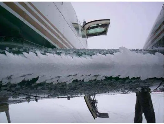
Apart from ice that is formed during flight at icing conditions, it must be made aware that there are also several other conditions that could contribute towards ice formation of aircraft airfoil. Lynch and Khodadoust (2001) had come up with several causes of ice formation on airfoil, without having to go through flight icing conditions. One of the most significant condition and that had also claims lives from flight accidents is by leaving the aircraft and its components in a bad weather conditions unprotected by ice protection systems such as shown in Figure 2.2.
Another significant factor that had been suggested by Lynch is ice formation on both lower and upper surfaces of the wings which is close to the fuel tanks. This condition occurs when an aircraft is parked in a high atmospheric humidity conditions and the fuels that has been cooled in flight remains in the tank and forms the ice. The delay or ignorance in implementing anti-icing procedure could also be the factor in ice formation on an aircraft airfoil. These findings shows that ice formation on airfoil will not just depends on icing conditions during flight, it also indicates that pre and post flight conditions could also be a contributing factor towards ice formation on airfoil.
7
2.1.3 COUNTERMEASURES FOR ICING CONDITIONS
For any icing conditions, the way the pilot approaches the problem is very important in order to ensure that the aircraft is not vulnerable to any danger regarding icing condition risks on the aircraft itself. There are several key countermeasures that need to be done carefully because any miscalculation could prove to be too risky to the safety of all the people onboard the plane. In this case, the experience and wise judgement of the pilot are very important because they are the one that will make any decision regarding the situation. Past accidents had shown that pilots sometimes tend to make ill judgement about icing condition that had resulted in accident. On 10th of March 1989, the pilot of Flight 1362 Air Ontario had decided to take off despite the fact that snow had accumulated rapidly on the wings of the plane. What happens next is history; the plane had crashed to nearby forest because the wing could not generate enough lift for the take off and crashes, claiming 24 lives. This is one of many other examples where bad decision had lead to fatal plane accident.
Hence, in order to face icing conditions, the pilot needs to take several countermeasures in order to ensure the plane will not be affected by any risks. According to Thomas (1999), the best decision if a fatal icing condition is present is not to fly at all, however this is not a very popular step to be taken. The pilot needs to be briefed of the incoming weather situation that will be encountered in order to ensure that are well prepared for the icing condition. When icing condition is present, the pilot could decide to adjust his or her cruising altitude in order to prevent from running into clouds that are potentially to create icing condition. Hence, this step is more to evasive action rather than reactive action.
8
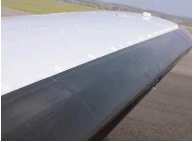
For most of modern planes, one of the most important instruments that need to be fitted to the aircraft is the de-icing boot which is a device that will eliminate any ice accretion for certain part of the plane especially the wing and the tail. According to Steve Ells (2004), there two types of active device to shake off ice accretions which are de-icing and also anti-icing. Anti icing is a more towards preventive measure where the device is turned on before the plane runs into any icing conditions. It is different to de-icing device (Figure 2.3) where it is more towards reactive measure because the device will only be turned on when there is ice formation on any part of the plane that is equipped with the device.