FIRE FIGHTING ROBOT
NORHAKEEM BIN MUSTAPA
This Report Is Submitted In Partial Fulfilment of Requirements for the Bachelor Degree Of
Electronic Engineering (Industrial Electronic) With Honours
Faculty of Electronics and Computer Engineering Universiti Teknikal Malaysia Melaka
ii
“Saya akui laporan ini adalah hasil kerja saya sendiri kecuali ringkasan dan petikan yang tiap-tiap satunya telah saya jelaskan sumbernya.”
Tandatangan : ………
iii
“Saya/kami akui bahawa saya telah membaca karya ini pada pandangan saya/kami karya ini adalah memadai dari skop dan kualiti untuk tujuan penganugerahan Ijazah Sarjana Muda Kejuruteraan Elektronik (Elektronik Industri).”
Tandatangan : ………. Nama Penyelia : ENGR. NUR ALISA BINTI ALI
iv
v
ACKNOWLEDGEMENT
In The Name of Allah, Most Gracious and Most Merciful,
vi
ABSTRACT
vii
ABSTRAK
viii
TABLE OF CONTENTS
CHAPTER TITLE PAGE
PROJECT TITLE i
REPORT STATUS DECLARATION ii
STUDENT DECLARATION iii
DEDICATION iv
ACKNOWLEDGEMENT v
ABSTRACT vi
ABSTRAK vii
TABLE OF CONTENTS viii
LIST OF TABLE xi
LIST OF FIGURE xii
I INTRODUCTION 1
1.1 Introduction 1
1.2 Objective 2
1.3 Problem Statement 2
1.4 Scope of Work 3
1.5 Report Layout 5
II LITERATURE REVIEW 6
2.1 Introduction 6
ix
2.4 Fire Fighting Robot (KMRF 40) 9 2.5 Fire Fighting Robot Contest #2 10
2.6 PIC Microcontroller 12
2.6.1 PIC 16 Family 14
2.6.2 Usage of PIC 16F877A
in A Fire Fighting Robot 15
2.7 Motor 16
2.7.1 DC Geared Motor with Encoder 16
2.8 Ultrasonic Sensor 17
2.8.1 HC-SR04 Ultrasonic Sensor 18
2.9 Flame Sensor Module 20
III METHODOLOGY 22
3.1 Introduction 22
3.2 Method of Project 23
3.3 Project Flow Chart 24
3.4 Project Consideration 29
3.5 Software Development 30
3.5.1 PIC Burner 30
3.6 Circuit Development 33
3.6.1 Main Circuit 34
3.6.2 Motor Circuit 35
3.6.3 Obstacle Avoidance Circuit 36 3.6.4 Flame Detection Circuit 37
3.6.5 The PCB Board 38
IV ANALYSIS AND RESULT 39
4.1 Introduction 39
4.2 PIC Microcontroller 40
4.2.1 Overview of Programming Instruction 41 4.2.2 Define Programming
x
4.2.4 Subroutines 43
4.2.5 Initialization 44
4.3 Circuit Development 45
4.3.1 Main Circuit 45
4.3.2 Motor Circuit 47
4.3.3 Motor Circuit Simulation 51
4.4 Hardware Development 53
4.4.1 Flame Sensor Plastic Filter Test 53
4.4.2 PCB Board Circuit 55
4.4.3 Body Frame Development 57
4.5 Progress Project 60
4.6 Product of Fire Fighting Robot 63
V CONCLUSION AND RECOMMENDATION 66
5.1 Conclusions 66
5.2 Recommendation 67
REFERENCES 68
xi
LIST OF TABLES
NO TITLE PAGE
2.1 The PIC microcontroller family and it features 13 2.2 Comparison between PIC16F877 and PIC16F877A 14
2.3 Type of motor 16
3.1 Project consideration component 29
4.1 Flame sensor module test raw source 53 4.2 Flame sensor plastic filter test (4 x thicknesses) 54 4.3 Explanation for each number tag from Figure 4.18 57 4.4 Explanation for each number tag from Figure 4.19 59 4.5 Explanation for each material use in robot construction
xii
LIST OF FIGURE
NO TITLE PAGE
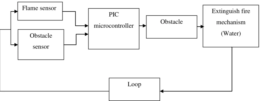
1.1 The whole processes for Fire Fighting Robot flow 2 2.1 Fire Fighting Robot made
by Howe and Howe technologies 7
2.2 Thermite scale and sketch drawing 7 2.3 Fire Fighting Robot made by Mikron123 8 2.4 Fire Fighting Robot made by Smarteam 9 2.5 Multi-purpose robot; weapons can be converted
to the camera 10
2.6 Autonomous Fire Robot made by ECE 290 Senior Design 10 2.7 Jonathan has 3 platform for space filling component 11
2.8 PIC16F877A 15
2.9 The DC geared motor with encoder 17
2.10 The HC-SR04 ultrasonic sensor 18
2.11 Sensor practical test of performance best of 300 angles 19
2.12 The timing diagram of HC-SR04 19
2.13 Flame sensor module 20
2.14 Flame sensor minimum 3 wires interface 21
3.1 Part 1 project flow 24
3.2 Part 2 project flow 26
3.3 Part 3 project flow 28
3.4 The USB ICSP PIC Programmer 31
3.5 The ICSP Programmer Socket 31
3.6 PICkit2 software interface 32
3.7 The circuitry planning for Fire Fighting Robot 33
xiii
3.9 Motor circuit diagram 35
3.10 Obstacle avoidance block diagram 36
3.11 Flame detection block diagram 37
3.12 The PCB board 38
4.1 Structure of PIC microcontroller 40
4.2 The main source code to initiate
the movement of the robot. 42
4.3 Subroutines for ultrasonic sensor 43
4.4 Subroutines for flame sensor 43
4.5 Initialization for motor 44
4.6 The main circuit 45
4.7 3D visualization of main circuit 46
4.8 Components position on main circuit 46 4.9 The DC geared and washer pump motor. 47
4.10 The H-Bridge 48
4.11 3D visualization of motor circuit 49 4.12 Components position on motor circuit. 50 4.13 Dc geared and washer pump motor circuit simulation 51
4.14 Voltage indicator on pin PIC 52
4.15 Hex.file Load Program into PIC using simulation 52
4.16 Green track removal machine 55
4.17 The etching machine 56
4.18 First 3D drawings for body frame development. 57 4.19 Second 3D drawings for body frame of robot. 58
4.20 Robot front view 60
4.21 Robot bottom view 60
4.22 Robot with mechanical equipment 61 4.23 Fire Fighting Robot before wiring installation 63 4.24 The ability of Fire Fighting Robot
in detecting flame and obstacles 63 4.25 Fire Fighting Robot side view
with complete circuit and sensor 64 4.26 Fire Fighting Robot front view
xiv
LIST OF ABBREVIATION
PIC - Peripheral Interface Controller
GND - Ground
HEX - Hexadecimal
ICSP - In-circuit Serial Programming DC - Direct Current
AC - Alternate Current
INOTEK - Innovation and Technology Competition
V - Voltage
xv
LIST OF APPENDICES
NO TITLE PAGE
A Flame Sensor Module Technical Datasheet 70
B Motor Specification 75
C L298 Dual Full-Bridge Driver Datasheet 76
CHAPTER I
INTRODUCTION
1.1 Introduction
2
Figure 1.1: The whole processes for Fire Fighting Robot flow
1.2 Objectives
The purpose of this project is to develop and design a Fire Fighting Robot guided by these following objectives:
a) To determine the use of multiple sensors for various sensing on the robot.
b) To develop a program to implement all the movement and behavior of the robot by using the PIC as the main control system design.
c) To design a robot that is able to avoid obstacles, detect fire next extinguish fire.
1.3 Problem Statement
Fire Fighting Robot is specifically designed for help humans, especially for firemen in the face of extinguishing fire situation. This robot uses can be applied at home or residential depending on how its operation. No matter it is used by firemen or individuals, the goal is only one which is to save lives when against the fire.
National Fire Protection Association has issued statistics on the number of firemen at the normal age suffering from line-duty deaths are due to heart attack by 25 percent, 21 percent die trapped by fire, 18 percent died after falling from a high
3
place and the rest suffer from cancer as a result of direct contact with chemicals and poisonous [1]. Firemen are more vulnerable to death in the course of their daily routine firefighting. The use of robots is one of the alternative medium for reducing firemen casualties and enhancing fireman capabilities.
Small fires from short circuits, gas stoves or other factors in the residence cannot be detected by human‟s sensitivity while robot design equipped with high sensitivity sensors can detect the presence of heat, smoke and fire. Unlike humans, the robot has a maximum capacity as alert, not tired and is able to perform 24 hours depending on the program of work specified in the robot [2].
The time factor is a problem in a fire situation. Small fire took just a few minutes before they become large, which may spread to other areas. Information through a phone call about a fire that was reported to firemen need time to determine the location of fire. The information of burning location must be recorded before the firemen go to that place. Moreover, the vehicle they are driving, large and difficult to pass through the traffic jam [3]. Through the production of fire fighting robot, the time can be reduced by placing the robot in a high-risk area of a fire.
Fire that occurred in nature is beyond human expectations. Fire caused by gas leak and chemical oil could cause an explosion, so dangerous to human life. Additionally degrees temperature level heat generated from the fire is beyond the capabilities of the human senses temperature [4]. The robot is capable doing its job in the area that is exposed to danger and able to perform the tasks at a high temperature.
1.4 Scope of Work
The potential of Fire Fighting Robot acts during extinguish flame, including: a) Detection of fire
4
Robot detects the presence of fire through the sensor within a range of 20cm to 100cm in designated areas. Sensitivity of sensing the fire is determined by calculating the distance from the robot to fire then the distance will be included in the PIC program.
Robot will avoid barriers if there have any obstacles that occur during the process of detecting fire. The distance between the robot and the obstacle is determined through calculations included in the PIC program.
The next step is itwill act to go to that place (fire) that have been detected by the sensor after move randomly and extinguish the fire with water. Focus on robot movement is based on flat surface work area.
All robot behavior is controlled by the Programmable Interface Controllers (PIC) as the main control system. PIC will control and give commands to the robot to sense the fire and obstacles. Assembly language is used as the language interface to be programmed in the PIC.
Robot has four wheels which consist of two servo wheels, and 2 castor balls driven by the DC geared motor (mounting with servo wheels). The use of these wheels is to facilitate the movement of the robot to move forward, backward and even to move in 1200 rotation in order to detect the flame and avoid obstacles.
Ultrasonic sensor is used as a sense of sight for Fire Fighting Robot. It is a sensor that will indicate obstacles in the path of movement. Ultrasonic sensor consists of a transmitter and receiver, transmitting to detect obstacles and receive signals through the receiver. Receiver will inform the PIC if there are obstacles in front of the robot. PIC will command the robot to change the direction of movement to avoid collisions with objects.
5
pump and pump water out of the tank. Water will then be channeled to the spray nozzle through a rubber pipe. Robot will act by extinguishing flame using water, until erased and return to the task of sensing a flame.
1.5 Report Layout
This thesis basically discussed about the design and development of Fire Fighting Robot. There will be five chapters that will describe and explain further about this project
Chapter I will describe about project introduction. This topic describes the introduction of the Fire Fighting Robot and the main objectives of the project. Overall topics include scope of the project; project methodology and the problem statement are included in this topic.
Chapter II will discuss Literature review topic. This topic focuses on the theory of every part of the robot design. Resources obtained from textbooks, journals, thesis and website containing all the information related to the project.
Chapter III will explain the methodology of project. This topic presents the steps to implement the project from the initial design to completion. Strategy and time planning are shows in this topic.
Chapter IV will inform the analysis and project result. This chapter describes the analysis and the development that was done in order to get better result to the project.
CHAPTER II
LITERATURE REVIEW
2.1 Introduction
7
[image:23.595.185.446.112.280.2]2.2 Thermite Fire Fighting Robot
Figure 2.1: Fire Fighting Robot made by Howe and Howe technologies [6].
Thermite is a Fire Fighting Robot that uses a remote control and can operate as far as 400m. This robot size 74 inches (187.96 cm) x 35 inches (88.9 cm) x 55 inches (139.7 cm). Referring to the figure 2.1, weight capacity for Thermite is 1.640 pounds (743.89 kg). Size is not too big and it is probable that Thermite can be carried anywhere. This robot powered up to 25 bhp (18.64 kW) by using diesel engine. Consumption aircraft aluminum grade manufacturing durable makes this robot easily across the extreme area. The main components in the design of this robot are multi-directional nozzle that is backed by a pump that can deliver 600 gallons per minute (2271.25 l/min).
[image:23.595.183.457.552.727.2]8
The Thermite is designed to be used in areas of extreme hazard, such as aircraft fires, refineries, chemical plants or nuclear reactors. Not only is it preferable to risk a robot instead of a person, the Thermite is also immune to smoke, fumes and fatigue. This robot is priced at U.S. $ 98.500 which is equivalent to RM302, 395 per unit.
[image:24.595.183.457.255.441.2]2.3 Fire Fighting Robot Contest #1
Figure 2.3: Fire Fighting Robot made by Mikron123 [7].
Referring to the figure 2.3, this Fire Fighting Robot is used to compete in robot competitions. The function of this robot is to find a candle that contains the fire, and then extinguish the fire. This robot can also function to save victim in the competition. The work area cover by this robot is in most rooms, stairs and sometimes can avoid obstacles.
![Figure 2.1: Fire Fighting Robot made by Howe and Howe technologies [6].](https://thumb-ap.123doks.com/thumbv2/123dok/546024.63908/23.595.183.457.552.727/figure-fighting-robot-howe-howe-technologies.webp)
![Figure 2.3: Fire Fighting Robot made by Mikron123 [7].](https://thumb-ap.123doks.com/thumbv2/123dok/546024.63908/24.595.183.457.255.441/figure-fighting-robot-mikron.webp)
![Post [2] SILABUS KELAS 5](data:image/gif;base64,R0lGODlhAQABAIAAAP///wAAACH5BAEAAAAALAAAAAABAAEAAAICRAEAOw==)