UNIVERSITI TEKNIKAL MALAYSIA MELAKA (UTeM)
LINEAR MOTION BASED SENSING TECHNIQUES
Thesis submitted in accordance with the partial requirements of the Universiti Teknikal Malaysia Melaka for the
Bachelor of Manufacturing Engineering (Hons)(Robotics and Automation)
By
MOHAMED AZRAAI B. AHMAD PUAD
B 050410225
UTeM Library (Pind.1/2005)
SULIT
TERHAD
TIDAK TERHAD
(Mengandungi maklumat yang berdarjah keselamatan atau kepentingan Malaysia yang termaktub di dalam AKTA RAHSIA RASMI 1972)
(Mengandungi maklumat TERHAD yang telah ditentukan oleh organisasi/badan di mana penyelidikan dijalankan)
(TANDATANGAN PENULIS)
Alamat Tetap:
NO 24, TAMAN SULTAN YUSOFF BUKIT KERAJAAN
33000 KUALA KANGSAR, PERAK
Tarikh:05/2008_________________
Disahkan oleh:
(TANDATANGAN PENYELIA)
Cop Rasmi:
Tarikh: _______________________
* Tesis dimaksudkan sebagai tesis bagi Ijazah Doktor Falsafah dan Sarjana secara penyelidikan, atau disertasi bagi pengajian secara kerja kursus dan penyelidikan, atau Laporan Projek Sarjana Muda (PSM). ** Jika tesis ini SULIT atau TERHAD, sila lampirkan surat daripada pihak berkuasa/organisasi berkenaan dengan menyatakan sekali sebab dan tempoh tesis ini perlu dikelaskan sebagai SULIT atau TERHAD.
BORANG PENGESAHAN STATUS TESIS* UNIVERSITI TEKNIKAL MALAYSIA MELAKA
JUDUL: LINEAR MOTION BASED SENSING TECHNIQUE
SESI PENGAJIAN: 2/2007-2008
Saya _____________________________________________________________________
mengaku membenarkan tesis (PSM/Sarjana/Doktor Falsafah) ini disimpan di Perpustakaan Universiti Teknikal Malaysia Melaka (UTeM) dengan syarat-syarat kegunaan seperti berikut:
1. Tesis adalah hak milik Universiti Teknikal Malaysia Melaka.
2. Perpustakaan Universiti Teknikal Malaysia Melaka dibenarkan membuat salinan untuk tujuan pengajian sahaja.
3. Perpustakaan dibenarkan membuat salinan tesis ini sebagai bahan pertukaran antara institusi pengajian tinggi.
4. **Sila tandakan (√)
MOHAMED AZRAAI BIN AHMAD PUAD
DECLARATION
I hereby, declared this project entitled “Linear Motion Based Sensing Technique” is the results of my own research except as cited in references
APPROVAL
This report submitted to the Senate of UTeM and has been accepted as partial fulfillment of the requirements for the degree of Bachelor of Manufacturing Engineering
(Robotics and Automation). The member of the supervisory committee is as follow:
………. Project Supervisor
May 2008
ACKNOWLEDGEMENT
I would like to express my appreciation to the individuals who had played a part in ensuring a successful occurrence and flow of activities throughout the duration of my Projek Sarjana Muda (PSM).
DEDICATION
This project and all the works that I have done were dedicated especially to my lovely mother that never stop from giving me advice and make me realize that I can do this project as long I don’t give up. I also dedicate this work to my father who support me mentally and financially until the end of my project.
ABSTRACT
In this report, there are explanations on how the sensor can be used to detect a linear motion, thus produce an output (electrical signal) that can be used for many applications whether in the manufacturing industries or daily works. But in this study, the application was focused on the linear motion of a milling machine.
The system for this study should have the capabilities to control the output or in other words have a multiple output. The main idea of this project was when the linear motion becomes faster; the output will be high, and when the linear motion becomes slower or stop, the output would stop. The systems generally have three major parts or sections where the parts were sensing system, processing system, and output system. Sensing system would have sensor to detect the motion, processing system have devices that can vary and stabilizes the output, while the output system have a motor where the motor speed depends on the output of second part. Sensing system must have a very good accuracy in order to give an accurate output. The elements that should have in processing system were good reliability and flexibility while in the output system, the element was high response.
ABSTRAK
Di dalam laporan ini, terdapat penerangan bagaimana ‘sensor’ digunakan sebagai alat untuk mengesan pergerakan linear, seterusnya membentuk satu aplikasi yang boleh digunakan dalam industri pembuatan atau dalam aplikasi seharian. Di dalam laporan ini, aplikasi dari tajuk ini difokuskan untuk mengesan pergerakan linear mesin ‘milling’.
Sistem untuk projek ini berupaya untuk mengawal hasilnya (dalam bentuk volt) atau dengan erti lain, boleh mengeluarkan keputusan yang pelbagai. Idea utama projek ini ialah apabila kelajuan pergerakan linear bertambah, maka volt yang keluar juga akan bertambah, manakala apabila kelajuan pergerakan linear tersebut berkurangan atau berhenti, maka volt yang terhasil adalah kosong. Secara umum, sistem ini mengandungi tiga bahagian dimana bahagian pertama ialah sistem pengesan, kedua ialah sistem pemprosesan dan ketiga ialah sistem keluaran.
Terdapat banyak factor yang perlu diambilkira dalam membentuk sistem ini, antaranya ialah rintangan, kestabilan arus (AC/DC), input, output, dan persekitaran. Bagaimanapun, setelah membuat kajian, akhirnya projek ini berjaya disiapkan dan semua objektif telah berjaya dicapai dimana output bergantung sepenuhnya kepada kelajuan pergerakan.
LIST OF FIGURES
Num Title Page
1.1 Graph Voltage vs Velocity 2 2.1 Sensor Position at Milling Machine 4 2.2 Parts in the System 5 2.3 The System Circuit 5
2.4 The Process Flow 7
2.5 Basic Design of IR Sensor 8 2.6 The Schematic Connection in IR Sensor 8 2.7 The DC Motor Speed Control Circuit 9 2.8 Connection between Motor and the Circuit 10 2.9 LM 2940 Voltage Regulator Circuit 10
2.10 LM 2917N Circuit 11
2.11 LM 3914N Circuit 11
2.12 The Infrared Sensor 12 2.13 LM 2940 Voltage Regulator 13
2.14 LM 3914N 13
2.15 LM 2917N 13
2.16 DC Motor 14
2.17 Accelerometer 22
3.1 Method Chart 25
3.2 Infrared Sensor Placement 26 3.3 Pulse/Frequency Input by Infrared Sensor 27 3.4 Infrared Connections 28 3.5 LM 2940 Voltage Regulator Circuit 29 3.6 LM 2917 N Connection 30 3.7 LM 3914 N Connection 31
3.8 Adaptor 32
4.1 Detection Model 34
4.2 Front View of Model 35 4.3 Inside View of Model 35
4.4 Second Part View 36
4.5 Inside of Second Part View 37 4.6 Control System Circuit 38 4.7 Output, the DC Motor 39 4.8 Top view of the Project 40 4.9 Side View of the Project 41 4.10 Sensor Output Graph 42 5.1 Equation Average Velocity and Average Acceleration 44
5.2 Current Equation 45
5.4 Graph Motor Speed vs Current 46 5.5 Graph Motor Speed vs Volt 47
LIST OF TABLES
Num Title Page
4.1 Output of Infrared Sensor 41
ix
LIST OF ABBREVIATIONS, SYMBOLS, SPECIALIZED
NOMENCLATURE
E&E - Electric and Electronic IR - Infrared Sensor
DC - Direct Current AC - Alternate Current
LVDT - Linear Variable Differential Transducer LVT - Linear variable Transducer
CONTENT
TITLE
PAGE
1.
Declaration
………..i
Approval…
………..ii
Acknowledgement
………..iii
Dedication
………...iv
Abstract
………v
Abstak
………..vi
List of Figure
………...vii
List of Table
………viii
List of Abbreviation, Symbols, Specialized Nomenclature
…...ix
2.
Chapter 1 - INTRODUCTION
1.1 Introduction ………..11.2 Background of Problem……….1
1.3 Objectives………..2
1.4 Scope……….3
1.5 Purpose of Study………...3
1.6 Conclusion……….3
3.
Chapter 2 – LITERATURE REVIEW
2.1 Introduction………...42.2 How System Work………5
2.2.1 First Part : The Sensing System ………..7
2.2.1(a) Infrared Sensor (IR)………..………..7
2.2.1(b) Sensor Features………9
2.2.1(c) Motor Speed Control………..………..9
2.2.2 Second Part: The Processing System……….10
2.2.4 System Picture………12
2.2.5 Devices Used………..15
2.3 Classification of Measurement Error……….16
2.4 Literature Review………...18
4.
Chapter 3 - METHODOLOGY
3.1
Introduction………..243.2
Mind Mapping...………...253.3
Motion Detection..………...263.4
Speed Detection………...………263.5
System Design………..283.5(a) The LM2940 Voltage Regulator………...…………28
3.5(b) LM 2917N………...……….29
3.5(c) LM 3914N………..………..………31
3.5(d) Capacitor Operation………...………...31
3.6
Current Stability………....…………...323.7
Application………...325.
Chapter 4 - RESULT
4.1 Introduction……….334.2 Parts Overview………….………..……….34
4.2.(a) First Part………..………34
4.2.(b) Second Part………..………36
4.2.(c) Third Part………..………..38
4.3 Completed Assembly………..39
6
Chapter 5 – DISCUSSION
5.1 Introduction………42
5.2 Description of Motion………43
5.3 Description of Motor……….44
5.4 Problems Overview………46
7
Chapter 6 – CONCLUSION
6.1 Introduction………486.2 Recommendation and Future Works………..49
8
REFERENCES
……….51C
HAPTER 1
INTRODUCTION
1.1 Introduction
Sensors are devices that detect the activity happen around it (environment). A sensor is a
type of transducer. Direct-indicating sensors, for example, a mercury thermometer, are
human-readable. Other sensors must be paired with an indicator or display, for instance a
thermocouple. Most sensors are electrical or electronic, although other types exist.
Sensors are used in everyday life. Applications include automobiles, machines,
aerospace, medicine, industry and robotics. Technological progress allows more and
more sensors to be manufactured on the microscopic scale as microsensors. In most cases
a microsensor reaches a significantly higher speed and sensitivity compared with
microscopic approaches
1.2 Background of Problem
There are many machines used linear motion as their movement to operate. From
this linear motion, we have made something or produced an output so that the motion will
not be wasted. So the idea was to make used of the linear motion and produced some
applications from it.
There are many complications in making the project to work, and most of them
came from the first and second system, that was sensing system and processing system.
For the sensing system, it took a lot of time to find a suitable sensor where almost all
electrical shop and internet websites have been explored, just to find the right sensor.
For the processing system, it required a system that can controlled the speed of
motor which depends on the output of sensor. There are many ways have been thought to
settle this problem such as using inverter, pendulum or even electronic circuit clock and
relays. But it seems that the most reliable device to be used in this part is by using the
Integrated Circuit (IC) circuit in the control system part.
The control system circuit consist of 3 ICs, resistors, capacitors, diodes,
transistors and chips like LM 2940 voltage regulators, LM 2917N, LM 3914N. LM
3914N is used to control the dim of the LEDs use in the project while LM 2940 is used as
voltage regulators that will fixed the output to 8V even the input voltage vary from 8 to
14 volts. For the LM 2917N, it is used to charge pump the input pulse that come from the
detector and turn it into voltage output.
1.3 Objective
The objectives of this project are like below:
Detect the linear motion speed
Control the motor speed (output) depends on the linear motion speed.
The voltage output will vary same as the linear motion speed.
When the linear motion speed is high, the output also must be high.
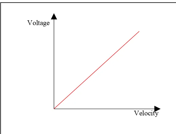
The main objective of this report was to make an output that came from linear motion of
an object or surface. The voltage output would be higher when the velocity increases and
would became lower when the linear motion’s velocity decreases. From the linear
motion, we could control the motor speed depend on how fast the motion was. Graph
below shows the voltage output versus velocity of linear motion.
Voltage
[image:17.612.170.467.478.705.2]Velocity
1.4 Scope
In this project, the final goal was to build a system that could detect the linear motion.
Although the task sounded like simple, it’s actually consumed a lot of hard work and time
in applying the knowledge in both electrical and mechanical. The circuit for controlling
the motor speed was manually constructed using the skills gained in electric and
electrical (E&E) subject. The sensor used to detect the linear motion was hard to find
because the sensor need to be reliable and could coped with the environment. After much
research, the method used was by using three IC circuits in the control system part while
for the detection, the infrared sensor was used.
1.5 Purpose of Project
This project can be said was a new invention although the sensor was already exists. The
application and the system were new and can be extended. It could utilize the unused
energy that was the kinematics energy came from linear motion. From the motion, an
output could be produced and another application could be done.
1.6 Conclusion
The project’s title was linear motion based sensing techniques and in this project, there
were three major parts, which were sensing system, processing system (the control
system part), and output system. The system was simple but was able to control the speed
of motor and also reliable.
CHAPTER 2
LITERATURE REVIEW
2.1 INTRODUCTION
The rapid development of sensor for example now with computer compatible output
signal has been remarkable since sensor being first introduced somewhere in 1970s. The
sensor technologies mostly were used in the industry sector where the usage of sensors
expends tremendously but nowadays there has been new applications and market sector
where new sensor technologies can be applied. This made the demand for sensor increase
for years by years.
For linear motion based on sensing techniques, there were sensors nowadays that can be
used to measure it but the use of sensors in this section still have a lot of potential to be
improved. The linear motions detection also has the capabilities to be applied in many
applications such as in industries and in the daily lives. There were so many examples of
linear motion in this world such as a moving car with the ground, milling machines,
surface grinder, and lathe machine. In this report, the application was focused in applying
the system with milling machine. Milling machine table moves horizontally and there
[image:19.612.369.515.480.700.2]was the place where the sensor would be placed to detect the linear motion.
Figure 2.1: Sensor Position at Milling Machine
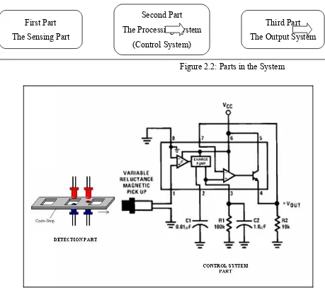
First Part
The Sensing Part
Second Part
The Processing System
(Control System)
Third Part
The Output System
2.2 How the System Works
As being stated in the abstract section, there were three major parts that consist in this
report system, that are sensing system, processing system, and output system. Each of the
section plays important role to make the system works and accomplished the objectives
of this report.
[image:20.612.82.541.228.635.2]5 Figure 2.2: Parts in the System
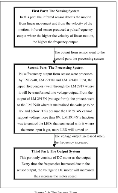
First Part: The Sensing System
In this part, the infrared sensor detects the motion
from linear movement and from the velocity of the
motion; infrared sensor produced a pulse/frequency
output where the higher the velocity of linear motion,
the higher the frequency output.
The output from sensor went to the
second part; the processing system
Second Part: The Processing System
Pulse/frequency output from sensor were processes
by LM 2940, LM 2917N and LM 3914N. First, the
input (frequencies) went through the LM 2917 where
it will be transformed into voltage output. From the
output of LM 2917N (voltage form), the process went
to the LM 2940 where it maintained the voltage to be
8V and below. This because the LM3914N cannot
support voltage more than 8V. LM 3914N’s function
was to control the LEDs that connected with it where
the more input it get, more LED will turned on.
The voltage output increased when
the frequency increased.
Third Part: The Output System
This part only consists of DC motor as the output.
Every time the frequencies increased due to the
sensor output, the voltage to DC motor will increased,
[image:21.612.107.501.58.701.2]thus increase the motor speed.
2.2.1 First Part: The Sensing System
In this part, a sensor was used to detect the motion. The output for this sensor
depending on the velocity of the linear motion where when the velocity is high,
the output will also be high. The Infrared Sensor was used to detect and its output
were in the form of frequencies or pulses where its output went through the
control system part as an input for the part.
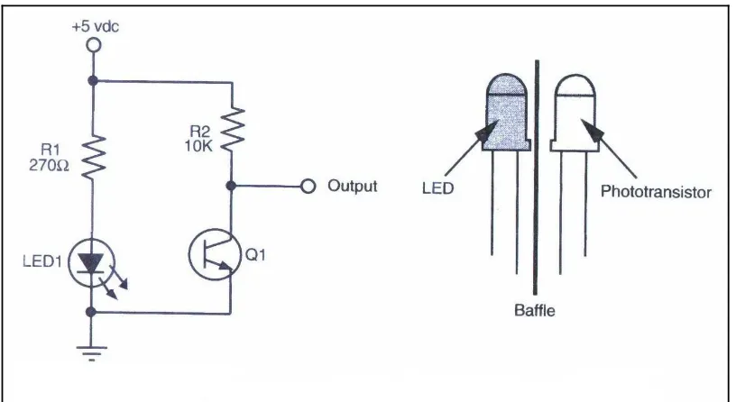
2.2.1(a) Infrared Sensor (IR)
Emissivity is a term used to quantify the energy-emitting
characteristics of different materials and surfaces. IR sensors
have adjustable emissivity settings, usually from 0.1 to 1.0,
which allow accurate measurements. For the emitter, an LED will be used
[image:22.612.123.531.364.587.2]where it will be detected by the sensor.
Figure 2.5: Basic design of IR sensor
2.2.1(b) Sensor Features
• User-scalable 0/4-20 mA or 0-5 V output
[image:23.612.115.515.78.303.2]• Local user-interface for sensor programming
• Optional laser sighting and high resolution optics
• Filed calibration software
• DataTemp MultiDrop Software compatibility
• Programmable relay outputs
• Bi-directional RS485 communications supports networks of up to
32 sensors