Engineering (Automotive)"
Signature
Supervisor's name En. Ir. Mochamad Safarudin
VEHICLE HANDLING IMPROVEMENT USING STEER BY WIRE TECHNOLOGY
YEW KHENG LOON
This report is submitted to the Faculty of Mechanical Engineering as a part of stipulation of bestowal Bachelor of Mechanical Engineering (Automotive)
Faculty of Mechanical Engineering Universiti Teknikal Malaysia Melaka
Engineering (Automotive)"
Signature
Supervisor's name En. Ir. Mochamad Safarudin
Signature
Name YEW KHENG LOON
To my lovely family
ACKNOWLEDGEMENTS
This Projek Sarjana Muda has emerged out of a great deal of research and simulation about Steer-by-wire technology, and I am gratefully acknowledge the following contributors to this project. They have played a vital role in helping me solve obstacles and give me a more thought provoking ways to done this project.
Ir. Mochamad Safarudin, Lecturer of Automotive Department and also my supervisor, Universiti Teknikal Malaysia Melaka, have been a constant source of advice. He has generously shared with me his knowledge and continues to encourage me to work individually with his guidance.
I also acknowledge my fellow friends, Choong Kei Shing and Amrik Singh, that have provide me clarity and technical support. Their support has smoothened and enhanced my overall progress.
ABSTRAK
ABSTRACT
TABLE OF CONTENT
CHAPTER CONTENT PAGE
ACKNOWLEDGEMENTS
ABSTRAK
ABSTRACT
TABLE OF CONTENT
LIST OF TABLE
LIST OF FIGURE
LIST OF SYMBOL
1 INTRODUCTION 1
1.1 RESEARCH BACKGROUND 1
1.2 PROBLEM STATEMENT 3
1.3 OBJECTIVES 4
1.4 SCOPE 4
2 LITERATURE REVIEW 5
2.1 Single Track Vehicle Model 5
2.2 The Fundamental Handling
Characteristic: Understeer, Oversteer And Neutral Steer
8
2.3 Tire Model 12
2.3.1 Pacejka Tire Model 13
2.3.1.1 Lateral Force, 13
2.3.1.2Aligning Torque, 14
2.4 Steer By Wire 15
2.4.1 Steering System Model 18
2.5 Virtual Reality 19
2.6 Steer-By-Wire Handling Improvement
19
2.6.1 Cornering Stiffness Handling
Modification 19
2.6.2 Proportional Integral Derivative
Controller 20
2.6.2.1 PID Tuning 23
3 METHODOLOGY 25
3.1 Flowchart 25
3.1.1 Literature Review 27
3.1.2 Mathematical Model of Single Track
Vehicle Model and Tire Model 27
3.1.3 Development of Simulink Model for Tire Model and Single Track Vehicle Model
27
3.1.4 Parameters Assignments 28
3.1.5 Simulation of Models 29
3.1.6 Models Validation 29
3.1.7 Development of Simulink Model of Tire Model and Single Track Vehicle Model for Steer by Wire
30
3.1.8 Tire Cornering Stiffness Modification 31
3.1.9 Manoeuvre Simulation 31
3.1.10 Steer By Wire Handling Improvement
Analysis 31
3.1.11 Virtual Reality Steer By Wire 32
3.1.12 Result And Discussion 35
3.2 Software Requirement 36
3.2.2 Simulink 36
3.2.3 3ds Max 2008 37
4 RESULT AND DISCUSSION 38
4.1 Single Track Vehicle Model 38
4.2 Steering System Model 41
4.3 Cornering Stiffness Modification 43
5 CONCLUSION AND
RECOMMENDATION 47
5.1 Conclusion 47
5.2 Recommendation 48
REFERENCE 50
BIBLIOGRAPHY 51
LIST OF TABLE
NO TABLE PAGE
2.1
Values of coefficients to for a car tire (Source: E.Bakker, L. Nyborg, and H.B. Pacejka, (1987))
15
3.1 Single track vehicle parameters 28
3.2 Steering system parameters 30
LIST OF FIGURE
NO FIGURE PAGE
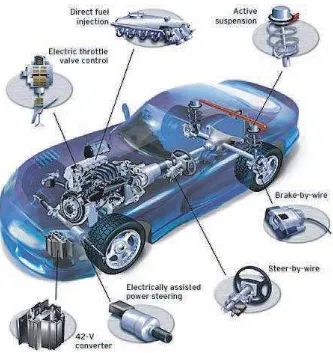
1.1
Automotive applications for by-wire technology
(Source: Motorola)
2
2.1 Single track vehicle mathematical model 6
2.2 Oversteer and understeer behaviour 11
2.3 Neutral steer ( = ) 11
2.4 Understeer ( > ) 11
2.5 Oversteer ( < ) 12
2.6 SAE tire axis terminology
(Source: Gim G. and Choi Y., (Nov. 2001)) 12
2.7
Characteristic of Magic Formula for fitting tire test data
(Source: Pacejka, H.B and Besselink, I.J.M. (1997))
15
2.8 Conventional steering system 16
2.9 Steer-by-wire system 16
2.10 Steer-by-wire steering system model 18
2.11 Steering system model 19
2.12 GraphPV against time, for three values of Kp
(Ki and Kd held constant) 22
2.13 Graph PV against time, for three values of Ki
(Kp and Kd held constant) 22
2.14 Graph PV against time, for three values of Kd
3.1 Single track vehicle model 28
3.2 Double lane change according to ISO 3888 29
3.3 PID controller 31
3.4 Tire in exploded view 32
3.5 Rack and pinion resemble with tires and
actuator 33
3.6 Steering assemble with actuator 33
3.7 Isometric view of simplify steer by wire 34
3.8 Interface simulink 34
3.9 VRsink block parameters 35
3.10 3ds Max 2008 37
4.1 Validation of vehicle model with double lane
change test 38
4.2 Double lane change steering angle 39
4.3 Graph of yaw rate for double lane change
validation 39
4.4 Validation of vehicle model with step steer test 40 4.5 Graph of yaw rate for step steer validation 40
4.6 Graph of desired steering input 41
4.7 Graph of actual steering input 42
4.8 Graph of steering input 42
4.9 Cornering stiffness modification model 43
4.10 Graph of yaw rate for cornering stiffness
modification 44
4.11 Graph of lateral acceleration for cornering
stiffness modification 45
4.12 Graph of sideslip angle for cornering stiffness
LIST OF SYMBOL
= Force
= Force at x-axis for front tire Fyr = Cornering force of rear tire Fyf = Cornering force of front tire
a = Distance from front axle to center of gravity b = Distance from rear axle to center of gravity δf = Front steering angle
αf = Front slip angle of tire αr = Rear slip angle of tire
= Saturated steering angle
ψ = Yaw angle
β = Sideslip angle
V = Velocity
Vx = Velocity at x-axis Vy = Velocity at y-axis
= Characteristic speed = Critical speed
= Longitudinal acceleration = Lateral acceleration
Ωz = Yaw acceleration
= Yaw rate
= Mass
= Acceleration = Lateral acceleration
= Moment
= Inertia at z-axis
= Front cornering stiffness = Rear cornering stiffness
= New front cornering stiffness
= Steer angle of the front wheel as a function of time = Wheel base
= Turning radius = Weight
= Front weight = Rear weight
= Acceleration due to gravity
= Coefficient of understeer gradient
B = Stiffness factor
C = Shape factor
D = Peak factor
E = Curvature factor
= Vertical shifts = Horizontal shifts
= Desired factional change in original front cornering stiffness = Desired steering angle
= Moment of inertia of the steering system at road wheel = Damping of the steering system at the road wheel = Steering ratio
= Torque magnification factor = Motor constant
= Motor current = Motor efficiency
CHAPTER 1
INTRODUCTION
1.1 Research Background
The design of automotive steering system has not changed much since the invention of steering wheel. Conventional automotive steering system mechanism is which the driver’s rotates the steering wheel according to driver’s input and the steering input will be transmitted through a shaft to the rack and pinion to generate steering motion at the front wheels. Hydraulic power steering assist is introduced first in the 1950s to improve steering performance. This type of power assist unit uses hydraulic pressure supplied by a motor-driven pump to amplify driver steering torque. The technical advantage of power assist unit is to ease driver steering effort and provide more safety factor by allowing the driver to swerve or change direction easily to avoid an accident.
According to Brian Daugherty, Douglas Cesiel and Michael C. Gaunt (2006), Steer-by-wire steering system is the same with the conventional automotive steering system except the mechanical linkages between the steering wheel and the front wheels are removed. The mechanical linkages are replaced with electronic sensors, controllers and actuators. By having more redundancy more sensors, controllers and actuators, the steer-by-wire can sustain higher fault-tolerant. However, by having more electronic component attach in the car, steer-by-wire suffer serious drawback of electrical power consumption. The present power supply commonly used in automotive is 12V, while all by-wire technologies needed 42V to operate at optimum performance.
Figure 1.1 : Automotive applications for by-wire technology. (Source: Motorola)
the design of car interiors. The steering wheel can be assembled easily into the dashboard for either left-hand or right-hand drive without the need of considering the steering column restriction. In addition, engine compartment will have more space utilization and able to design a bigger engine. Moreover, by removing the mechanical linkage, noise, vibration and harshness from the road will no longer be felt directly by the driver thru the steering wheel.
Another advantage is the variable steering ratio of the steer-by-wire system optimizes the steering response and driver steering wheel feel. In city driving, this ratio should be smaller in order to reduce the hand wheel torque and rotation. Finally, by removing steering column of the vehicle, it significantly decreases the weight of the vehicle and thus reduces fuel consumption. In 2004, BMW 5-Series have manufactured an almost steer-by-wire vehicle. The car has equipped with active steering system and demonstrates handling improvements that a steer-by-wire can achieved.
1.2 Problem Statement
1.3 Objectives
The objectives of this paper are to build a steer-by-wire mathematical model, to build a Simulink model, to apply control strategies to improve handling and to simulate vehicle handling improvement using the control strategies.
1.4 Scope
CHAPTER 2
LITERATURE REVIEW
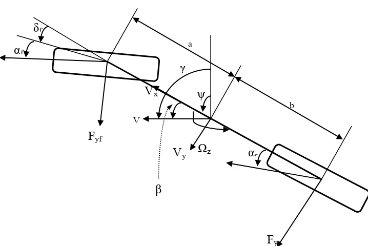
2.1 Single Track Vehicle Model
Figure 2.1: Single track vehicle mathematical model
Derivation of the equations of motion for the bicycle model follows from the force and moment balance:
Taking counter clockwise direction as positive
β
ψ
V
Vy Vx
γ
Fyr Fyf
δf αf
b
αr a
The total cornering stiffness of the front and rear tires:
Taking small angle approximations, slip angle can be written as;
The equation with respect to the axes fixed to the vehicle body are given by,
Assuming the steer angle is small and constant longitudinal velocity , the equation of lateral and yaw motions of a vehicle with steer angle as input,
=
+
r +
= + r +
2.2 The Fundamental Handling Characteristics: Understeer, Oversteer, And
Neutral Steer
The bicycle model is useful for describing a vehicle’s fundamental handling characteristics. One way to approach an explanation of handling characteristics using the bicycle model is to define a term known as the understeer gradient. The prime factors controlling the steady state handling characteristic of a vehicle are the weight distribution of the vehicle and the cornering stiffness of the tires.
The cornering force on the front and rear tires and can be determined from the dynamic equilibrium of the vehicle in the lateral direction. For small angles, the cornering forces acting at the front and rear tires are approximately given by