Vision System for Autonomous Underwater Vehicle Using Wireless Camera for
Monitoring and Surveillances Application
M. Shahrieel (1), A.Nadhirah(1), M.Farriz(2) (1)
Department of Mechatronics, FKE UTeM, [email protected], [email protected] (3)
Department of Power Industry, FKE UTeM, [email protected]
Abstract This paper present the new design of vision system for autonomous underwater vehicle with the
implementation of wireless camera, whereby, produce clearer image. The major obstacle faced by underwater vision system is the extreme loss of color and contrast when submerged to any significant depth whereby the image quality produced is low. Therefore, as to obtain clearer images, several investigations will be done in order to know the appropriate distance required between the images with the camera. At the end of the project, the new design of the vision system will be well functioned and can be applied to capture clearly the underwater images and also might be used to explore the nature of underwater. This new vision system also could be used for monitoring, surveillances, and maintenance tasks for underwater where it is risky for the human to work in it.
Introduction
Water is the major composition on earth as it covered 70% of earth surface. However, it seems difficult for human to explore the underwater nature. The major obstacle faced by the underwater vision system is the extreme loss of color and contrast when submerged to any significant depth whereby the image quality produced is low. The ocean is currently the largest body of mass which covered seventy percent of Earth, but still remains the least explored. Modern area of research and development had discovered some equipment that can be used for the underwater application and the latest invention is designing the Autonomous Underwater Vehicles (AUV). It has the potential in furthering the exploration of the deep sea.
Implementation vision system together with AUV would be the most efficient system created for capturing and recording underwater images. This invention had replace the conventional waterproof camera that been used before. Lots of benefits earn from this new system such as this system is ease to conduct and convenient to be use.
The application of this vision system can be widen so that the usage of the system is not only limited for exploring the underwater environment, but also can be used in education, research and rescue. However, in order to build this system, it might used higher cost as it design and the system’s ability are quite complex. Therefore, this project had been proposed as to design more simple design of vision system for AUV with a lower cost.
Theory
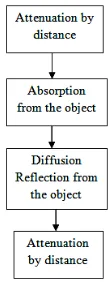
Whatever method that been proposed to improve the underwater images, the most important basic improvement is actually based on color space conversion, chromaticity histograms, color equalization and normalization. Basically, the color perception of an object is depends on physical, physiological and psychological and components such as spectral composition of light, spectral reflectance of the object, transmission of the light in the medium, and the visual system of the observer. Figure 1 illustrated the process of underwater color modification.
Fig. 1: Underwater color modification.
prey or the Navy inspecting objects without being detected. As for active system, the underwater imaging use generated source of light. A simple example is an underwater camera system which uses either strobe or continuous artificial illumination [1].
There a few terms that need to be highlighted when discussing about an image which are image processing, image analysis, robot vision and machine vision. There is a significant overlap in terms of techniques and applications that been used. This implies that the basic techniques that are used and developed in these fields are more or less identical, something which can be interpreted as there is only one field with different names.
Those classifications are used to demonstrate the relationship between image range, camera light separation and the limiting factors in underwater image collection. If only short ranges are desired, a simple system with a controlled light beam and a good camera can yield excellent pictures as underwater photographers know. If longer ranges are desired, the separation of lights and cameras presents substantial advantages in that backscatter can be reduced substantially. Fig. 2 illustrated the concept for each group [2]
Fig. 2: Classification System for Underwater Image Collection Systems
Design Procedure
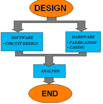
The processes that need to be highlighted in this project are divided in to two sections which are hardware and fabrication as shown in Fig. 3. The analysis of the project can only be done after these two parts is well done. As for hardware part, it involve on circuit design of LED which is presented as a flash to the lens of the camera. The fabrication section will include on chosen the right material and features for the outer casing of the wireless camera.
After both sections were ready, the next step
particular stage. Detailed result will be explained in this paper.
As for the final stage it might involve with several troubleshooting and testing. Seems that all the equipment that been used are not for the underwater application, therefore, several problem or malfunction of the system might occurred. However, after several troubleshooting is done as to ensure that the project can be proceeding with a detailed analysis. Fig. 3 shows the flow chart of the process in completing the project. Fig. 4 is shown the cicruit design. A simple LED circuit had been design as to provide enough light intensity to the vision system for AUV as shown in Fig. 5.
Fig. 3: Overall Methodology of the Project
Each of white LED gives a voltage drop of 3.6V. For a 12V light, a maximum of 3 white LEDs in series at full power only can be used which will result, 3.6 x 3 = 10.8V volts drop. Subtract this from supply voltage of 12V to get the additional voltage. Thus, 12 - 10.8 = 1.2V. Current flow in the circuit is calculated using ohm’s Law, I= V / R =1.2 / 27= 44.44mA. In order to ensure the resistor can handle enough current. So in this case, 12 volts x 44.44mA = 0.53W. Therefore the power consumed would be 0.53W.
Fig. 6: water proof casing of project
This project needed a full attention on the hardware and fabrication part as both parts will drive to the successfulness of the project’s objective. In terms of hardware design, it is important to ensure that the circuit is well function as it will provide enough light intensity when it is been apply for underwater environment. As for the fabrication part, the type of casing that been chosen is very important because the casing need to be water proof so that when it is applied for underwater purposes, it might not cause any failure either to the circuit or to the camera as shown in Fig. 6
.
Results
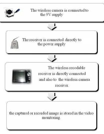
Several tested had been done as to ensure that the setting of the video monitoring and the wireless camera will give the response of clear image. Fig. 5 shows the step to set up the wireless camera with the video monitoring. When all the equipments had been set up, the power supply is switch on and the frequency at the receiver is tuned so that the wireless recordable receiver will view the image.
Fig. 5: Process to set up the equipments
Analysis is done for this particular project as to prove the ability of this new vision system either it can view the clearer image or not. The main purpose of this analysis is to captured clear image that had been submerge in the water. As for this analysis, the vision system that been created is undergone the analysis by capturing the images from three different sample of water.
The image that had been captured will be ranting based on the image description of the image. Tab. 2 shows the image rating and description that need to be considered in order to rating an image [4].
Tab. 2: Rating of Image
Rating Description
Excellent 10 An image extremely high quality, as good as could be desire. Fine 8 An image of high quality,
providing enjoyable viewing. Passable 6 Image is acceptable a quality
image.
Marginal 5 Image is poor in quality
Inferior 3 Very poor quality of an image but still could watch it.
The testing is being done in three different conditions of water which are in the clear water, mix-up water with detergent as well with the sludge water. Different conditions or type of water environment are selected because different environment might yield different result for determining the appropriate distance for producing clearer underwater images as shown in Fig. 6.
Fig. 6: Performance versus distance for three different types of water.
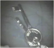
Here we changing the indicator for rating to point form for analysis . Indicator 10 is excellent and 1 unusable as shown in Tab. 2. Fig. 7, Fig. 8 and Fig. 9 shows the result that had been obtained for the distance of 10 cm between the object and the vision system.
Fig. 7: Clear Water environment
Fig. 8: Water Detergent
Fig. 9: Sludge Water
It is clearly shows that even though the image had been captured in the same distance, the result yield is slightly different. The image produce for the clear water environment tend to be very clear. However the image that been produce in mix-up water detergent and the sludge water are tend to be a little bit blur. Throughout this analysis, a few interpretations can be made which are:
Overall, the capability of this system to identify the object or the image is with the average of 0.4m between the object and the vision system.
As mention earlier, different environment of water might yield different result in determining the clear image. It is due to noise and as well with the different particles existing in the water.
In crystal clear water, the distance of the vision system to the object might be in the range of 0.1m-0.3m as to capture clear image.
In the second environment which is water detergent, the suitable range of distance that can produce clear image would be between 0.15m-0.1m.
For the last conditions, sludge water, in order to obtain clear image for this particular type of water, it is important to ensure that the distance of the vision system to the object is in the range of less than 0.1m.
Conclusions
References
1 Arnold-bos, et al. (n.d.). A preprocessing Framework for Automatic Underwater Images Denoising. Retrieved February 8, 2009, from www.nxp.com/acrobat_download/applicationnote s/APPCHP3.pdf
2 Camera. (n.d.). History of Camera. Retrieved September 18, 2008, from http://www. chuckgroot.com/ShortHistoryofCameras.html 3 Gonzalez, R. C., & Woods,R. E. (2002). Image
Enhancement in The Spatial Domain. Digital Image processing (pp. 75-146). New Jersey: Prentice Hall.
4 Gonzalez, R. C., & Woods,R. E. (2002). Image Compression. Digital Image processing (pp. 420). New Jersey: Prentice Hall.
5 Huat Lim D. L. (2004, November 1). Definition of Autonomous Underwater Vehicle. Design of Vision System for Autonomous Underwater Vehicle.
6 Raynolds J. (1998, October). Problem of Underwater Vision. Autonomous Underwater Vehicle: Vision System.
7 Wireless Camera. (n.d). OmniVision CMOS (Silver). Retrieved January 5, 2009, from http://www.geeks.com/details.asp?invtid=CM208 CA&cat=VID
8 Wireless.(n.d.).Concept of Wireless. Retrieved October 8, 2008, from http://en.wikipedia. org/wiki/Wireless