PARKING BRAKE TESTER
AHMAD HAZWAN BIN FAUZI
This report is submitted in partial fulfillment of the requirements for the Bachelor in Mechanical Engineering (Structure and Materials)
Faculty Mechanical Engineering Universiti Teknikal Malaysia Melaka
ii
DECLARATION
I hereby declare that this project report entitled
PARKING BRAKE TESTER
is written by me and is my own effort and that no part has been plagiarized without citations.
Signature : ………...
iii
DEDICATION
To my beloved parents,
Fauzi bin Ismail and Fatimah binti Zakaria. Who inspired me with their love and kindness.
iv
ACKNOWLEDGEMENTS
I would like to generously thank many people that assisted and supported my Projek Sarjana Muda (PSM). This PSM report is the product of hard work with several people. A special thanks to our beloved lecturer, Mr Herdy Rusnandy, who was continually encouraging, insightful, and help me throughout this project. Without his guidance and useful advice, I don’t think my PSM report can be finished successfully and on time. I would like to thanks to my friends whom I had the pleasure to meet and work with in my project.
A special appreciation also to my friends who kindly help me by providing interesting discussions and insights that helped me achieve a larger perspective in my PSM report. Last but not least, my family should be thanked. They have stood by me and watched my study evolve for the better. They have also been a source of constant support, encouragement and financially help me. Finally, I would like to thank everyone who is willing to spend their precious time reading my PSM report.
v
ABSTRACT
vi
ABSTRAK
vii
TABLE OF CONTENT
CHAPTER TOPIC PAGE
DECLARATION ii
DEDICATION iii
ACKNOWLEDGMENTS iv
ABSTRACT v
ABSTRAK vi
TABLE OF CONTENT vii
LIST OF TABLES viii
LIST OF FIGURES ix
LIST OF NOMENCLATURE x
CHAPTER 1 INTRODUCTION 1
1.1 Background 1
1.2 Objective 2
1.3 Scope 2
1.4 Problem Statement 2
CHAPTER 2 LITERATURE REVIEW 3
2.1 Parking 3
2.2 Brake 4
2.3 Brake Maintenance 5
2.4 Gauges 6
2.4.1 Strain Gauge 6
2.4.2 Bourdon Meter 9
viii
CHAPTER TOPIC PAGE
CHAPTER 3 METHODOLOGY 12
3.1 Introduction 12
3.1 Research Process 13
3.1.1 Problem statement 14
3.1.2 Literature Review 14
3.1.3 Specification & Criteria 14
3.1.4 Designing / Planning 15
3.1.5 Final Design 18
3.1.6 Design 19
3.1.7 Fabrication 19
3.1.8 Testing 19
3.1.9 Conclusion 20
3.3 Summary of Methodology 20
CHAPTER 4 RESULT 20
4.1 Parking brake Tester 20
CHAPTER 5 DISCUSSION 26
5.1 Force Analysis on Parked Vehicle 26
5.2 Maximum Inclination angle 29
viii
LIST OF TABLE
TABLE TITLE PAGE
Table 3.1 Polar Modulus Section Table 19
ix
LIST OF FIGURE
FIGURE TITLE PAGE
Figure 2.1 Strain Gauge Structure 6
Figure 2.2 Strain Gauge Wiring Diagram 7
Figure 2.3 Bourdon meter 8
Figure 2.4 Bourdon Meter Parts 9
Figure 2.5 Parking Brake Assembly 10
Figure 3.1 Flow Chart 13
Figure 3.2 Gauge Setup Diagram 18
Figure 4.1 Test Rig 24
Figure 4.2 Hydraulic Parking Brake 24
Figure 4.3 Electric Parking Brake 25
x
LIST OF NOMENCLATURE
T = Torque on wheel
Zp = Polar modulus of section
τ = shearing stress
ν = Poisson Ratio
1
CHAPTER 1
INTRODUCTION
1.1 Background
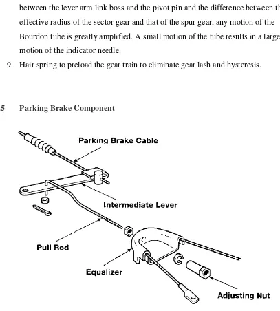
2 brake that uses cable, it actually transmits the lever movement through a typical series of components such as pull rods, parking brake cable, intermediate lever, equalizer, adjusting nuts.
1.2 Objective
To design and fabricate the parking brake tester that can simulate the real parking brake system and the condition of the real car
1.3 Scope
The scopes of this project are: a) Study the parking brake system
b) Determine the measurable forces and torque in parking brake system c) Investigate suitable location for gauges in parking brake
d) Design and fabricate parking brake tester
e) Test and evaluate the performance of parking brake tester
1.4 Problem Statement
4
CHAPTER 2
LITERATURE REVIEW
2.1 Parking
Parking is the act of stopping a vehicle and leaving it unoccupied for more than a brief time. It is against the law virtually everywhere to park a vehicle in the middle of a highway or road; parking on one or both sides of a road, however, is commonly permitted. Parking facilities are constructed in combination with most buildings, to facilitate the coming and going of the buildings' users.
5 Inner city parking lots are often temporary, the operators renting land which is vacant pending the construction of a new office building. Some inner city lots are equipped with individual lifts, allowing cars to be stored above each other. Another ad hoc arrangement is tandem parking. This is sometimes done with residential motor vehicle parking where two motor vehicles park nose-to-end in tandem. The first motor vehicle does not have independent access, and the second motor vehicle must move to provide access. As with attendant parking, the purpose is to maximize the number of motor vehicles that can park in a limited space.
2.2 Brake
Brake is a compulsory device in every vehicle. In fact, brake invented along with the vehicle invention in order to slow down and stopping the movement of the vehicle. There are several types of brake that is air brake, hydraulic brake and mechanical type. The kinetic energy lost by the moving part is usually transformed to heat by friction. Note that kinetic energy increases with the square of the velocity (E = 1/2·m·v2 relationship). This means that if the speed of a vehicle doubles, it has four times as much energy. The brakes must therefore dissipate four times as much energy to stop it and consequently the baking distance is four times as long. Even some airplanes are fitted with wheel brakes on the undercarriage.
Friction brake on cars stores the heat inside the disc rotor or the drums and gradually releases the heat away to the air. That’s why we can see some ventilated disc rotor and drum with some fin in order to spread heat faster and more efficient. Ventilated disc rotor usually installed on the front wheel as the force and load are more concentrated to the front wheel rather than the rear.
6 to some people as they concern about the gearbox condition. Maintaining a brake system is quite cheap when you suffer a gearbox breakdown.
2.3 Brake Maintenance
Some research revealed that the brake fluid absorb water from the surroundings 12% annually. When water accumulates in the brake line, the brake fluid will become less responsive due to the changes in the chemical characteristics. It also changes the boiling point of the fluid hence making the fluid less effective dealing with heat as brakes also produces heat and the heat is greater when braking force is applied harder and more frequent. A long stretch of going downhill really putting your brake system under heavy stress and this can lead to brake malfunctioning if maintenance is not a consideration. Because of this reason, some manufacturers suggested that the brake fluid needed to be flushed every 100000 km but this numbers are different according to manufacturers.
Then, the brake system also needed to be checked for wear and tear especially the pads and the brake shoe/lining. There are also the retract pin at the caliper that tends to wear with prolong usage and it can give an unpleasant screeching sound as it does not travel in the right axis. There is also thickness limitations of the disc rotor usually stated on the disc plate itself. Otherwise, one can refer to the manual if it does not state on the disc. Disc rotor also tends to warp in certain conditions.
Drum brakes with internal shoes have a particular disadvantage; when the drums
are heated by hard braking the diameter of the drum increases due to the expansion of
the material and the brakes must be further depressed to obtain effective braking action.
This increase of pedal motion is known as brake fade and can lead to brake failure in
extreme circumstances. For this reason drum brakes have been superseded in most
modern automobiles and light trucks with at least front wheel (often now four wheel)
7
advantages. An advanced technology hybrid car using drum rear brakes is the Toyota
Prius. (Hybrid vehicles greatly reduce everyday wear on braking systems owing to their
energy recovery motor-generators). Early type brake shoes contained asbestos. When
working on brake systems of older cars, care must be taken not to inhale any dust
present in the brake assembly. Since the introduction of ceramic and kevlar linings, a
majority of daily-driven older vehicles have been fitted with asbestos-free linings since.
2.4 Gauges
2.4.1 Strain Gauge
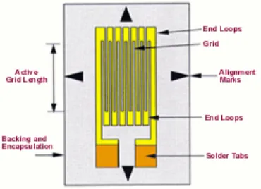
The strain gauge has been in use for many years and is the fundamental sensing element for many types of sensors, including pressure sensors, load cells, torque sensors, position sensors, etc. The majority of strain gauges are foil types, available in a wide choice of shapes and sizes to suit a variety of applications. They consist of a pattern of resistive foil which is mounted on a backing material. They operate on the principle that as the foil is subjected to stress, the resistance of the foil changes in a defined way.
Figure 2.1 Strain Gauge structure
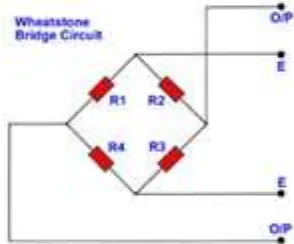
8 precision resistors. The complete Wheatstone Bridge is excited with a stabilised DC supply and with additional conditioning electronics, can be zeroed at the null point of measurement. As stress is applied to the bonded strain gauge, a resistive changes takes place and unbalances the Wheatstone Bridge.
Figure 2.2 Strain Gauge wiring diagram
Analogically, if a strip of conductive metal is stretched, it will become skinnier and longer, both changes resulting in an increase of electrical resistance end-to-end. Conversely, if a strip of conductive metal is placed under compressive force (without buckling), it will broaden and shorten. If these stresses are kept within the elastic limit of the metal strip (so that the strip does not permanently deform), the strip can be used as a measuring element for physical force, the amount of applied force inferred from measuring its resistance.
Such a device is called a strain gauge. Strain gauges are frequently used in mechanical engineering research and development to measure the stresses generated by machinery. Aircraft component testing is one area of application, tiny strain-gauge strips glued to structural members, linkages, and any other critical component of an airframe to measure
9
A strain gauge's conductors are very thin: if made of round wire, about 1/1000 inch in diameter. Alternatively, strain gauge conductors may be thin strips of metallic film deposited on a nonconducting substrate material called the carrier. The latter form of strain gauge is represented in the previous illustration. The name "bonded gauge" is given to strain gauges that are glued to a larger structure under stress (called the test specimen) The task of bonding strain gauges to test specimens may appear to be very simple, but it is not. "Gauging" is a craft in its own right, absolutely essential for obtaining accurate, stable strain measurements. It is also possible to use an unmounted gauge wire stretched between two mechanical points to measure tension, but this technique has its limitations.
10
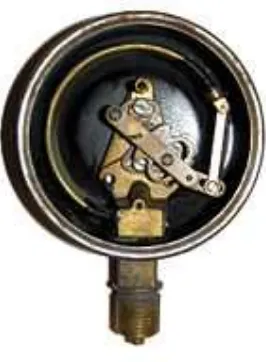
2.4.2 Bourdon Meter/Pressure Meter
Figure 2.3 Bourdon meter (with back cover removed)
11
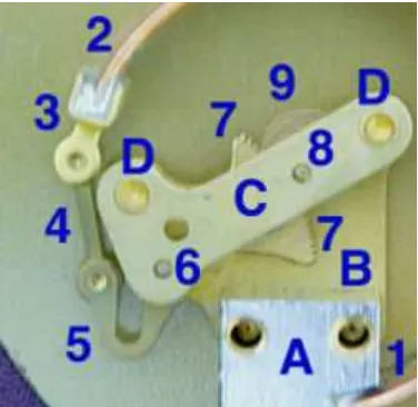
Figure 2.4 Bourdon Meter parts
Mechanical Details Stationary parts:
• A: Receiver block. This joins the inlet pipe to the fixed end of the Bourdon tube (1) and secures the chassis plate (B). The two holes receive screws that secure the case.
• B: Chassis Plate. The face card is attached to this. It contains bearing holes for the axles.
• C: Secondary Chassis Plate. It supports the outer ends of the axles. • D: Posts to join and space the two chassis plates.
Moving Parts:
1. Stationary end of Bourdon tube. This communicates with the inlet pipe through the receiver block.
2. Moving end of Bourdon tube. This end is sealed. 3. Pivot and pivot pin.
4. Link joining pivot pin to lever (5) with pins to allow joint rotation. 5. Lever. This is an extension of the sector gear (7).
12 8. Indicator needle axle. This has a spur gear that engages the sector gear (7) and
extends through the face to drive the indicator needle. Due to the short distance between the lever arm link boss and the pivot pin and the difference between the effective radius of the sector gear and that of the spur gear, any motion of the Bourdon tube is greatly amplified. A small motion of the tube results in a large motion of the indicator needle.
9. Hair spring to preload the gear train to eliminate gear lash and hysteresis.
2.5 Parking Brake Component
Figure 2.5 Parking brake assembly
13
CHAPTER 3
METHODOLOGY
3.1 Introduction
There are several types of method that had been adopted to accomplish the
objectives of this study. The research methodology for this research includes discussion on
the method of previous fabrication, the approaches that had been used, and data analysis.
The project flow depend on the flow chart that been prepared and the explanation for every steps will be described in this chapter. This chapter also will be discussed based from chapter 2.
3.2 Research Process
The research process for this study can be divided into 2 phases. In the first phase,
the research will involve the literature reviews which include common information about
parking brake or the testing system,. From the findings of the literature review, specimen
sample had been developed according to the specimen specifications that have been choose
and the standard test procedure will be carried out. The data conducted from test was