170
DEVELOPMENT OF A QUADRUPED CRAWLING ROBOT PROTOTYPE
A.Noordin1, a M.A.Salim2, b*, M. R. Sapiee3, c, S. Sabikan4, d, M.H.C. Hasan5, e, Z. Md. Sani6, f, M.H. Othman7, g
1,3,4,5Faculty of Engineering Technology, Universiti Teknikal Malaysia Melaka, Hang Tuah Jaya, 76100 Durian
Tunggal, Melaka, Malaysia. aEmail: [email protected]
2Faculty of Mechanical Engineering, Universiti Teknikal Malaysia Melaka, Hang Tuah Jaya, 76100 Durian Tunggal,
Melaka, Malaysia .bEmail: [email protected]
6,7
Faculty of Electrical Engineering, Universiti Teknikal Malaysia Melaka, Hang Tuah Jaya, 76100 Durian Tunggal, Melaka, Malaysia.
Abstract— Although wheeled robots are commonly used, it has limited ability to move to any terrains at ease. They suffer from difficulties when travelling over uneven and rough terrains. Legged robots have an advantage over the wheeled robots in that they are suited for such situations. The implementation of legged robots normally requires many motors to move every joint in a robot leg. Additional motor will increase the construction cost, robot weight, and the
demand for power supply. Moreover, robot
simulation becomes more complex. This research is related to the design and development of a cost effective quadruped autonomous robot. The robot can moves according to a unique pattern using three servo motors as its actuator in each of its leg. The design of the robot is firstly made with CAD program and then the structure of the body and the leg is analyzed in order to find a correct balance and to make sure the servo motors are capable to move the robot. A prototype of the quadruped robot is fabricated and tested thoroughly. Experimental studies are carried out to test its stability issues when the robot moves. The robot is capable of moving forward, backward, turn left and turn right by crawling its way. A microcontroller is used as the brain of the robot assisted by two analog distance sensor for better obstacle sensing. It uses a rechargeable battery as the power supply for the microcontroller. The servo motors on the other hand are powered by another rechargeable battery. At the end of this research, a working prototype has been developed.
Keywords—Quadruped robot, crawling robot.
I. INTRODUCTION
Robotic technology is expanding rapidly. Mobile robots and artificial intelligence era have colored the robotic field nowadays. A lot of researches had been conducted by researchers in university and multinational companies, and even by the military, to understand the high mobility and stability of autonomous robot on rough terrain. Mobile robots are very useful in a situation where it is fatal or dangerous
for human act. An example of the application using mobile robot is the scanning of buried land mine [1].
Mobile robots consist of two types; the wheeled and legged robots. Wheeled robots are more common as they are easier to design and build. The cost of building a wheeled robot is generally low or cheaper. However, the wheeled robots are more suited to application on fairly even terrains as they are less adaptable when crossing uneven or rough terrains. Legged robots are trickier to design and built as compared to the wheeled robot. This is due to the complexity in designing the actuator and joint. To build a legged robot, the stability factor and also the coordination of movement of the leg robot must be considered [1].
There are many types of leg robots. Famous types of the robot that many researchers tend to build are bipedal robot, quadruped robot and 6-legged robot. There are many four legged animals that have ideal mobility traits, thus a large number of four legged robots have been built in an effort to emulate nature’s proven techniques. An attractive aspect of such a platform is that they can achieve static stability by planting at least three of their legs on the ground and maintaining their center of mass over this three leg tripod. With such a gait, the robot may stop and hold its position at any instant of its execution without losing stability. These robots are inherently slow and have poor power efficiencies not only from the requirement of static stability, but also owing largely to the many degrees of freedom in their legs. Their legs’ complexity, coupled with the large mass of many actuators, limit the robot’s behavior and lend the robots to frequent breakdowns.
A robot is a machine that senses, thinks, and acts. Thus, a robot must have sensors, processing ability that emulates some aspects of cognition, and actuators. Sensors are needed to obtain information from the environment [1]. Reactive behaviors such as the stretch reflex in humans do not require any deep cognitive ability, but on-board intelligence is necessary if the robot is to perform significant tasks autonomously, and actuation is needed to enable the robot to exert forces upon the environment. Generally, these forces will result in motion of the entire robot or one of its elements such as an arm, a leg, or a wheel.
171
i. A robot should never harm a human being. ii. A robot should obey a human being, unless this
contradicts the first law.
iii. A robot should not harm another robot, unless this contradicts the first or second law.
The British Robot Association (BRA) defines robot as:
"A programmable device with a minimum of four degrees of freedom designed to both manipulate and transport
parts, tools or specialized manufacturing implements through variable programmed motion for the performance of the specific manufacturing task”. .
II. LOCOMOTION TECHNIQUE
The term locomotion actually means ability or the power to move. Therefore, locomotion technique can be concluded as a method for something to move. For legged robot, basically there are two types of locomotion techniques which are static and dynamic locomotion.
For static locomotion as shown in Figure 1, because of their center of gravity is always within their ground contact base, robots that use this type of locomotion are always balanced. There are many robots that have been successfully develop using this technique but since it is more similar to wheel movement, it can only retain fewer advantages. Even though legged robot that use this techniques can move and walk at uneven terrain compared to wheel robots but this type of robots are very inefficient as power is put into every movement. However, robots that use static locomotion are a lot easier to control rather than robots that use dynamic locomotion techniques. direct one, due to the fact that there isn't only one solution and in some cases there are an infinity number of solutions. To solve this problem the Jacobian's Math Method is the most used [4].
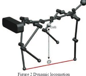
For static locomotion technique as shown in Figure 2, while lifting one of the legs, the other three legs are supporting the whole body weight. Even if all the joints not moving, the robot will not fall. However, this type of locomotion is slow and not efficient.
Figure 1 Static locomotion
Dynamic locomotion is unstable and often falls because the robots are not always in balance. Many robots that use dynamic walking are continually falling and thus much more energy efficient. Therefore in order to control the robot using this technique, it requires much more complex control systems to avoid falling. However, robots that use this technique can achieve many more advantages over wheeled locomotion.
A subset of dynamic walking is called passive dynamic movement. Most dynamic walking systems use active control to move the legs to the correct orientations for walking which is active dynamic walking. Passive dynamic walking is characterized by a system where gravity and inertia alone generate the locomotion pattern. Passive dynamic movement can be achieved with maximum efficiency, as the vehicle uses its own forward momentum to propagate its next movement. Very little energy is lost from the system.
Figure 2 Dynamic locomotion
Dynamic gait requires extremely little control in order for them to walk, and rely largely on the natural physics mostly the effects of gravity of the walker in order to produce a stable gait. This class of walkers demonstrates the fact that a walk need not have any gait planning, and requires very little energy. Basically, the model for dynamic gait planning is very complex and requires much time and experience in order to produce the motion stability of a quadruped robot.
172
III. RESEARCH METHODOLOGY
In developing this quadruped robot, there are several numbers of tasks involved. Figure 3 shows the general ideal for research methodology of this study.
Figure 3 Flow chart of research methodology
Inside this section, a series of experiment have been done to acquire the performance of the quadruped walking robot. The objectives of the experiments were:
i. To find link transformation matrix of the robot. ii. To find suitable gait for the robot to move forward. iii. To test whether the robot able to avoid obstacles in
front of it.
iv. To investigate whether the robot can move at various terrains or not.
v. To evaluate the accuracy and repeatability of the robot.
In order to find the link of transformation matrix, there a few steps need to be followed and there are:
i. Identify the joint axes and imagine infinite lines along them. For steps 2 through 5 below, consider two neighboring axes (i and i+1).
ii. Identify the common perpendicular, or point of intersection, between the neighboring axes. At the point of intersection, or at the point where the common perpendicular meets the ith axis, assign the link frame origin.
iii. Assign the Zi axis pointing along the ith joint axis. iv. Assign the Xi axis pointing along the common
perpendicular, or if the axes intersect, assign Xi to be normal to the plane containing the two axes. v. Assign the Yi axis to complete a right-hand
coordinate system.
vi. Assign the {0} frame to match the {1} frame when the first joint variable is zero. For the {N} frame choose an origin location and XN direction freely, but generally so as to causes many linkage parameters as possible to become zero.
These steps are referred to Denavit-Hartenberg Parameters.
IV. ROBOT DEVELOPMENT
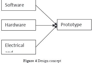
This section is discussed about overall process in developing a prototype of quadruped walking robot. Generally, a design process can be divided into three main categories which are hardware, electrical/electronic parts and software. Figure 4 shows the ideas of the design concept.
Figure 4 Design concept
The hardware part of the robot consists of several parts which are body, sensor brackets, servo brackets, U-joints
YES
Sketchinganddesign
Materialselection
Integrationofelectric
andelectronic Fabrication
Developsoftware
algorithm Gaitplanning
Testingandanalysis
173
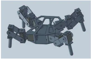
and robot legs. Figure 5 shows the general idea of the robot.
Figure 5 General idea of robot
According to the general idea of the design, this quadruped robot consists four legs which have three servo motors at each leg. This means that the robot have three degree of freedom (DOF). For this type of robot to move forward, one of the legs will be lifted one by one. The robot will not fall when moving forward and can move fluently.
At early stage of the design process, the idea of the robot was transferred into 3D drawing using computer aided design software. This step is very important to obtain an initial overview of the structure of the robot without spending much time and money. Large sums of money needed to build a robot. Thus, small errors involving the design of a robot should be avoided so that the cost to build the robot can be reduced. Figure 6 and
Figure 7 show two different design of the robot that has
been made. The most suitable design has been selected in term of performance and whether it is possible to be fabricated.
After some consideration, the second design was chosen instead of first design since the first design is quite hard to fabricate. Another reason was the foot of the robot leg contact with ground is very small thus the robot encounters difficulties to move forward.
Figure 6 First design of the robot
Figure 7 Second design of the robot
Several problems have been encountered when constructing the robot by using the second design. But the problem was not big so as to affect the overall performance of the robot. The first problem was the foot of the robot was very slippery. The robot was difficult to stand up let alone moving forward. As a result, rubber pad was used at the ‘feet’ of the robot leg as a solution.
Figure 8 (a) and (b) shows the fabricated leg without and
after a rubber pad is attached at the end of it feet.
(a) (b)
Figure 8 (a) Robot feet (b) Robot feet with rubber pad The second problem was to connect the U-joint with the servo brackets. The front side of the U-joint was connected with servo motors while the back side of the U-joint connected with the servo bracket. The problem arises on how to connect the servo bracket and the U-joint since if just tighten it with only screw, the bracket will not move when the servo was rotating. Hence the ball bearing was used to solve this problem. The solutions for this problem are shown at Figure 9 and Figure 10
respectively. Overall, most of the robot part is fabricated using rapid prototyping machine as shown in Figure 11
174
Figure 9 Front side of servo bracket
Figure 10 Back side of servo bracket
Figure 11 Rapid prototyping machine
V. RESULTS AND DISCUSSION
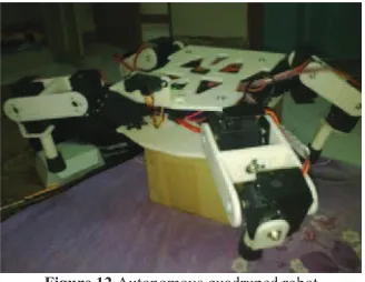
Figure 12 shows the real model of the quadruped robot and it was developed in study. This robot use Mini Maestro 18-servo controller that act like as a ‘brain’ of this robot. Each leg of this robot consists of three servo motor that indicates the robot has three degree of freedom. The robot is powered up by using two 7.4V Li-Po batteries which supply the servo controller board and servo motors. This robot also equipped with an analog distance sensor. This robot can move forward without falling and can avoid obstacles in front of it.
Figure 12 Autonomous quadruped robot
In robotic world, Denavit-Hartenberg principle is widely used to select frame of references. The Denavit-Hartenberg notation gives a standard methodology to robotics engineers to write the kinematic equations of a manipulator. This is especially useful for serial manipulators where a matrix is use to represent the position and orientation of one body with respect to another.
Based on link frame attachment procedure by Denavit-Hartenberg, the entire joint at each leg of the robot was assigned. Figure 13 shows the link frame assignment sketch at one the leg diagram. Since all the leg is similar, therefore only one leg will be analyze and discussed.
Figure 13 Link frame assignment
From the link frame assignment, D-H table for the leg was constructed and record in Table 1 below:
Table 1 D-H Table
i
1 0 0 0 0
2 90 55 40 0
3 0 80 0 0
175
General expression of link transformation:
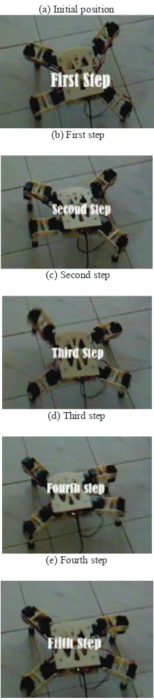
0 position. Leg 1 was lift and move forward about 20° from initial position. By the time leg 1 touching the ground, leg 3 was lift and move forward about -20°. At the same time leg 1 move back to the initial position. By the time leg 3 touch the ground, leg 2 was lift and move forward about -20°. At the same time leg 3 moves back at initial position. After leg 2 touches the ground, immediately leg 4 was lift and move 20° forward. At the same time, leg 2 moves Figure 14 Moving forward gait
The summary of the gait is shown at the graph in
176
Figure 15 Graph of gait representation
VI. CONCLUSIONS
This study has been successfully carried out and achieved its objectives in terms of mechanical and electronic design, locomotion of the autonomous four legged robot and programming. This quadruped walking robot has ability to move forward and detect obstacles thus avoid it. By using twelve units of servo motors and each leg consists of three degree of freedom (DOF), the autonomous four legged robot have similar gait pattern likes other quadruped animals.
ACKNOWLEDGEMENT
The authors would like to acknowledge to Universiti Teknikal Malaysia Melaka for supporting this work through a short term grant.
.
REFERENCES
[1] T.W. Tee, K.H. Low, H.Y. Ng, Fredrick Young, Mechatronics Design and Gait Implementation of a Quadruped Legged Robot. Seventh International Conference on Control, Automation, Robotics and Vision (ICARCV'O2). Dec 2002. [2] David Wettergree, Robotic Walking in Natural Terrain - Gait
Planning and Behavior-Based Control for Statically-Stable Walking Robots. Carnegie Mellon University Ph.D, 1995. [3] Isaac Asimov’s page [Online] Available 2010:
http://www.androidworld.com/prod22.htm.