UNIVERSITI TEKNIKAL MALAYSIA MELAKA
STUDY OF AIRFLOW ON THE FIXED HORIZONTAL
LOUVERS SHADING DEVICE FOR COMMERCIAL BUILDING
This report is submitted in accordance with the requirement of the Universiti Teknikal Malaysia Melaka (UTeM) for the Bachelor Degree of Manufacturing
Engineering Technology (Product Design) with Honours
by
KOID SHI HONG B071210377 910425-08-6587
UNIVERSITI TEKNIKAL MALAYSIA MELAKA
BORANG PENGESAHAN STATUS LAPORAN PROJEK SARJANA MUDA
TAJUK: Study of Airflow on the Fixed Horizontal Louvers Shading Device For Commercial Building
SESI PENGAJIAN: 2015/16 Semester 1
Saya KOID SHI HONG
mengaku membenarkan Laporan PSM ini disimpan di Perpustakaan Universiti Teknikal Malaysia Melaka (UTeM) dengan syarat-syarat kegunaan seperti berikut:
1. Laporan PSM adalah hak milik Universiti Teknikal Malaysia Melaka dan penulis. 2. Perpustakaan Universiti Teknikal Malaysia Melaka dibenarkan membuat salinan
untuk tujuan pengajian sahaja dengan izin penulis.
3. Perpustakaan dibenarkan membuat salinan laporan PSM ini sebagai bahan pertukaran antara institusi pengajian tinggi.
4. **Sila tandakan ( )
SULIT
TERHAD
TIDAK TERHAD
(Mengandungi maklumat yang berdarjah keselamatan atau kepentingan Malaysia sebagaimana yang termaktub dalam AKTA RAHSIA RASMI 1972)
(Mengandungi maklumat TERHAD yang telah ditentukan oleh organisasi/badan di mana penyelidikan dijalankan)
Alamat Tetap:
iv
Koid Shi Hong
08th January 2016
DECLARATION
I hereby, declared this report entitled “Study of Airflow Around the Fixed Horizontal Louvers Shading Device For Commercial Building” is the results of my own
research except as cited in references.
Signature :………
Name : ………
v
APPROVAL
This report is submitted to the Faculty of Engineering Technology of UTeM as a partial fulfillment of the requirements for the degree of Bachelor of Manufacturing Engineering Technology (Product Design) with Honours. The member of the supervisory is as follow:
vi
ABSTRACT
vii
ABSTRAK
viii
DEDICATIONS
This report is dedicated to my beloved parents, my siblings and not forgets my friends, who always support and encourage me during this final year project work. Last but not least, my final year report group mates who were always there when I
ix
ACKNOWLEDGMENTS
First of all, I would like to take this opportunity to express my sincere gratitude to my supervisor Engr. Mohd Faizal Bin Halim from the Faculty of Engineering Technology, Universiti Teknikal Malaysia Melaka (UTeM) for his guidance, supervision and support towards the process of this final year project report.
Besides that, I would also like to send my gratitude to Mr. Ismail Bin Abu Shah and Mr. Mohd Qadafie Bin Ibrahim for evaluating my final year project. Several inputs which were suggested earlier had given me an idea and guidance to improve my final year project.
In addition, I would like to thank Faculty of Engineering Technology (FTK), Universiti Teknikal Malaysia Melaka (UTeM) for giving a fully support and allows me to utilize the facilities equipment’s which are available in laboratories.
x
TABLE OF CONTENTS
DECLARATION ... iv
APPROVAL ... v
ABSTRACT ... vi
ABSTRAK ... vii
DEDICATIONS ... viii
ACKNOWLEDGMENTS ... ix
TABLE OF CONTENTS ... x
LIST OF FIGURES ... xiv
LIST OF TABLE ... xvi
LIST OF EQUATION ... xvii
LIST OF SYMBOLS AND ABBREVIATIONS ... xviii
CHAPTER 1 ... 1
1.0 Background of Study ... 1
1.1 Problem Statement ... 2
1.2 Objectives ... 3
1.3 Scope of Work ... 4
CHAPTER 2 ... 5
2.0 Overview ... 5
2.1 Louver Application ... 5
xi
3.6.5 Element Quality Checks ... 36
xii
3.6.7 CFD Volume Meshing ... 38
3.6.8 Transition to AcuConsole ... 39
3.7 Solver ... 39
3.8 Post Processing ... 42
CHAPTER 4 ... 44
4.0 Overview ... 44
4.1 25 Degree Louver Fin ... 45
4.1.1 Qualitative Result ... 45
4.1.2 Quantitative Result ... 46
4.2 35 Degree Louver Fin ... 47
4.2.1 Qualitative Result ... 47
4.2.2 Quantitative Result ... 49
4.3 45 Degree Louver Fin ... 50
4.3.1 Qualitative Result ... 50
4.3.2 Quantitative Result ... 51
4.4 Effect of Wind Velocity ... 52
4.4.1 25 Degree ... 53
4.4.2 35 Degree ... 55
4.4.3 45 Degree ... 58
4.5 Discussion and Comparison of Results ... 61
4.5.1 Pressure Difference at Difference Louver Fin Angle ... 62
4.5.2 Difference between Inlet and Outlet Velocity ... 64
xiii
5.0 Conclusion ... 67
5.1 Suggestion for Future Work ... 68
APPENDIX A ... 70
APPENDIX B ... 74
xiv
LIST OF FIGURES
Figure 1.1: Aluminium Louver ... 2
Figure 2.1: Building Bacony Fixed Aluminium Window Louver ... 6
Figure 2.2: Security Gate Systems with Combination of Louver ... 6
Figure 2.3: Solar Shading for Commercial Building Usage ... 7
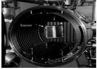
Figure 2.4: Installation of Thermal Louver at The Cryogenic Vacuum Chamber ... 7
Figure 2.5: Exploded View of Louver ... 8
Figure 2.6: Primary Louver Parameters ... 10
Figure 2.7: Louver Models with Different Blade Angle ... 11
Figure 2.8: Pressure Loss of Each Louver ... 12
Figure 2.9: Proportion of Pressure Loss Lowering ... 12
Figure 2.10: The Effective Emittance Through the Opening Angle ... 13
Figure 2.11: Shapes of Louver Straight, Bent Tip, Concave, and Convex From Left to Right ... 14
Figure 2.12: Effect of Restitution Coefficient on Collection Efficiency of The Configuration ... 15
Figure 2.13: The Relation Between Air Change and Wind Velocity ... 16
Figure 2.14: Boundary Conditions Used in The Computational Simulation ... 17
Figure 2.15: Quadrilateral (Boundary Layer) Grid Used Around Each of The Louvers ... 18
Figure 2.16: Two-Dimension CFD Model ... 19
Figure 2.17: Meshes in Louver ... 19
Figure 2.18: The Different Flow Fields Showed By CFD Prediction ... 22
Figure 3.1: Flow Chart ... 25
Figure 3.2: Schematic Diagram for Hydraulic Diameter ... 27
Figure 3.3: Residual Ratio ... 28
Figure 3.4: Mesh Independence ... 29
Figure 3.5: Geometry Model in SolidWork ... 31
Figure 3.6: Geometry Model in SolidWork ... 32
Figure 3.7: Solid and Surface Deleted ... 32
Figure 3.8: Distance of Nodes between Duplicated and Created ... 33
Figure 3.9: Lines Created from Nodes ... 33
Figure 3.10: Enclosing Surfaces ... 34
Figure 3.11: Nodes and Surfaces Deleted ... 34
Figure 3.12: Nodes and Surfaces Deleted ... 35
Figure 3.13: Boundary Condition ... 35
Figure 3.14: Meshing ... 36
Figure 3.15: Element Quality Check ... 37
Figure 3.16: BL Parameter and Created Components ... 38
xv
Figure 3.19: Auto Solution Strategy Panel ... 40
Figure 3.20: Auto Solution Strategy Panel ... 40
Figure 3.21: Solution Boundary Condition ... 41
Figure 3.22: Launch AcuSolve Panel... 42
Figure 3.23: AcuFieldView Result ... 42
Figure 3.24: Probe Surface for Exact Value ... 43
Figure 4.1: Point of Measured ... 44
Figure 4.2: Vector Result for 25° ... 45
Figure 4.3: Contour Result for 25° ... 45
Figure 4.4: Vector Result for 25° ... 46
Figure 4.5: Pressure Difference at 25° Louver Fin ... 47
Figure 4.6: Vector Result for 35° ... 48
Figure 4.7: Contour Result for 35° ... 48
Figure 4.8: Vector Result for 35° ... 48
Figure 4.9: Pressure Difference at 35° Louver Fin ... 49
Figure 4.10: Contour and Vector Result for 45° ... 50
Figure 4.11: Contour Result for 45° ... 50
Figure 4.12: Vector Result for 45° ... 51
Figure 4.13: Pressure Difference at 45° Louver Fin ... 52
Figure 4.14: Contour Result for 25° at Difference Inlet Velocity... 53
Figure 4.15: Vector Velocity Result for 25° at velocity 4 m/s ... 53
Figure 4.16: Vector Velocity Result for 25° at velocity 8 m/s ... 53
Figure 4.17: Vector Velocity Result for 25° at velocity 12 m/s ... 54
Figure 4.18: Pressure Difference for 25° at Difference Velocity ... 55
Figure 4.19: Contour Result for 35° at Difference Inlet Velocity... 56
Figure 4.20: Vector Velocity Result for 35° at velocity 4 m/s ... 56
Figure 4.21: Vector Velocity Result for 35° at velocity 8 m/s ... 56
Figure 4.22: Vector Velocity Result for 35° at velocity 12 m/s ... 57
Figure 4.23: Pressure Difference for 35° at Difference Velocity ... 58
Figure 4.24: Contour Result for 45° at Difference Inlet Velocity... 59
Figure 4.25: Vector Velocity Result for 45° at velocity 4 m/s ... 59
Figure 4.26: Vector Velocity Result for 45° at velocity 8 m/s ... 59
Figure 4.27: Vector Velocity Result for 45° at velocity 12 m/s ... 60
Figure 4.28: Pressure Difference for 45° at Difference Velocity ... 61
Figure 4.29: Pressure Difference against Z Distance ... 62
Figure 4.30: Pressure Difference against Louver Fin Angle... 63
Figure 4.31: Difference between Inlet and Outlet Velocity ... 64
xvi
LIST OF TABLE
Table 2.1: Result of Changing Separator Parameter ... 10
Table 3.1: Relation between Number of Elements and Maximum Pressure ... 29
Table 4.1: Pressure at 25° Louver Fin ... 46
Table 4.2: Pressure at 35° Louver Fin ... 49
Table 4.3: Pressure at 45° ... 51
Table 4.4: Collected Data at Difference Inlet Velocity for 25°... 54
Table 4.5: Collected Data at Difference Inlet Velocity for 35°... 57
Table 4.6: Collected Data at Difference Inlet Velocity for 45°... 60
Table 4.7: Pressure Difference against Z Distance ... 62
Table 4.8: Pressure Difference against Louver Fin Angle ... 63
Table 4.9: Difference between Inlet and Outlet Velocity ... 64
xvii
Equation 2.1: Drag Coefficient………...………14
Equation 3.1: Mass Conservation Equation………26
Equation 3.2: Momentum Conservation Equation………...26
Equation 3.3: Reynolds Number……….27
Equation 3.4: Hydraulic Diameter………..27
xviii
LIST OF SYMBOLS AND ABBREVIATIONS
Δp = Pressure Difference
° = Degree
2D = Two Dimensional
3D = Three Dimensional
=
= Kinematic Viscosity, Pa s
= Air Density,
= Inlet Pressure (Pa)
= Outlet Pressure (Pa)
= Reynolds Number
= Inlet Velocity
= ,
1
CHAPTER 1
INTRODUCTION
1.0 Background of Study
In the 21st century, the world faced the environment problems like increasing surface temperature, change in wind speed and etc. that was reported in the Intergovernmental Panel on Climate Change, 2007. For instant, temperature of Malaysia had increased 0.18 °C per decade for over 40 years since 1951 (Ministry of Science, Technology and Innovation, MOSTI, 2000). According to Malaysia Meteorological Department (METMalaysia), the climate characteristic features for Malaysia are uniform temperature, high humidity, copious rainfall and light on the wind. The average wind speed at Malaysia is 3.8 m/s.
2
However, the performance of the louver is still questionable and mostly their function only to serve as an esthetical function of the building. Furthermore, the performance of the louver is based on its design parameter such as, blade angle, number of louver, blade shape and area ration (Musgrove, G. et al., 2009).
In this project, a louver design for commercial buildings will be studied by using Computational Fluid Dynamics (CFD) simulation. The aim of this study is to improve the performance of the louver ventilation.
Figure 1.1: Aluminium Louver (Adapted from Ruskin company)
1.1 Problem Statement
3
parameters according to the market demand and most of the time the efficiency of louver has been neglected. The common size of louver that can found in the market is 50.8 to 152.4 mm for depth while, 2 mm aluminium plate are used to fabricate the blades and frame up to various lengths and the height dimension. Even though, the blade angles also have a variety of degree but, generally manufacture will produce 25, 35 and 45 degree (Nakanishi, T. et al., 2007). As the blade angle increase, the free space between the blades will increase, thus it enables more air pass through the louver and increase the velocity. Moreover, after install some of the problems still happened like, not enough airflow passes through the louvers, excessive water penetration, and not enough movement of the operable blade (Livingston. J., 2006). Therefore, it is important to identify the optimum angle of the louver design.
1.2 Objectives
The main goal of this project is to improve the performance of the louver for building application. The objectives of this project are included:
4 1.3 Scope of Work
In this project, louver with geometry model 4.6 x 1.2 x 0.3 meter for the length, height and width will be generating at initially. In order that, the depth of louver will be 101.6 mm and aluminium plate with 10 mm thickness is selected to construct the CAD data. Since, the design parameter is desired; so, the calculation and report are based on louver without a bird or insect screen.
5
CHAPTER 2
LITERATURE REVIEW
2.0 Overview
This chapter will define about all findings obtained from several literature reviews, which may come from any resources like journal, technical paper, article and books about the topic that are related in this project. The topics discussed in this chapter will be louver application, louver structure, design parameter and computational fluid dynamics (CFD). After that, all of the collected information will be implemented in this project.
2.1 Louver Application
The main function of louver is act as a ventilation system for the building by exhaust air extracted from building and providing fresh air flow. Besides that, with the combination of aesthetics and ventilation feature, louver can be a gate for security purpose.
6 2.1.1 Housing
In particular, the louver applied by the housing is medium range and usually used as door or window shutter. The distinctive foiled blades can be incorporated into any style or simply used in a stand-alone situation when applied at glazing, door, gates and etc.
Figure 2.1: Building Bacony Fixed Aluminium Window Louver
(Retrieved from http://www.alibaba.com/aluminum-fixed-louver-promotion.html)
Furthermore, louver can be used as a housing secure option. The frames are made from stainless steel or aluminium box section which attaches the blades along the frames.
7
The louvers install at the commercial building should withstand strong wind force because they have large surface area. During the construction process, increased the structure should be concerned to strong up the points of attachment. Otherwise, louvers also can attach to columns or vertical stringers in order to increase or change the support structure (Carson, J., 2010).
Figure 2.3: Solar Shading for Commercial Building Usage
(Retrieved from The blinds help manage overheating, and they are backed up by a geothermal cooling system, Dewjo, 2009)
2.1.3 Vacuum Chamber
In a vacuum chamber, thermal louver is installed in the middle of the chamber. For this kind of louver, movable or rotating shutters over a radiating surface is applied because it able to acquire highly efficient devices for controlling the temperature of a spacecraft (Braz, J., et al. 2001).