i
DESIGN AND DEVELOPMENT OF RECREATIONAL
HUMAN POWERED VEHICLE
MUHAMMAD HANIF BIN MOHD ZANANI
This report is submitted in
fulfillment of the requirements for the award
Bachelor of Mechanical Engineering (Design & Innovation)
Faculty of Mechanical Engineering
UniversitiTeknikal Malaysia Melaka
ii
SUPERVISOR DECLARATION
“
I hereby declare that I have read this thesis and in my opinion this report is sufficient in terms of scope and quality for the award of the degree ofBachelor of Mechanical Engineering (Design-Innovation)
”
iii
DECLARATION
“I hereby declare that the work in this report is my own except for summaries and
quotations which have been duly acknowledged.”
Signature:
...
Author: MUHAMMAD HANIF BIN MOHD ZANANI
iv
SPECIAL DEDICATION
TO
My Beloved Parents
En.MohdZanani bin JamilNorsamsinahbintiSuboh
Also my beloved siblings
Muhammad Hazim bin MohdZananiMuhammad Hasif bin MohdZanani Muhammad Hamidi bin MohdZanani
v
ACKNOWLEDGEMENTS
Praise and glory to the almighty Allah S.W.T., God of all creation. In the
name of Allah, the Beneficent, the Merciful, my greeting and salutations towards our
beloved Prophet Muhammad S.A.W for overseeing this final year project with
constantly guiding toward completion.
My heartfelt gratitude is extended to my dedicated supervisor; Mr.
MohdNizam bin Sudin for giving me his guidance and support throughout this
project. His experience in topics related to this project has given me a boost of
confidence in conducting this project. Therefore, special thanks to him for the
opportunity given and for the efforts towards the completion of this final year
project. My big thanks also go for all technicians at faculty‟s lab. Their technical
assists, are very helpful upon completion of fabricating my project‟s prototype.
vi
ABSTRACT
vii
ABSTRAK
viii
TABLE OF CONTENTS
CHAPTER SUBJECT PAGE
TITLE i
SUPERVISOR’S DECLARATION ii
AUTHOR’S DECLARATION iii
DEDICATION iv
ACKNOWLEDGEMENT v
ABSTRACT vi
ABSTRAK vii
TABLE OF CONTENTS viii
LIST OF TABLES xi
LIST OF FIGURES xii
LIST OF SYMBOLS / TERMS xvi
LIST OF APPENDICES xvii
CHAPTER I INTRODUCTION
1.1 Background 1
1.2 Objectives 3
1.3 Scope of product 3
1.4 Project Schedule 5
CHAPTER II LITERATURE REVIEW
2.1 History of human powered vehicle 6 2.2 Types of human powered vehicle 11
2.3 Quadracycle 12
2.4 Current Technology oh Human Powered vehicle 13
2.4.1 Current Market 14
2.4.2 Green Technology Involvement 15 2.5 Human Powered Vehicle Parts 17
2.5.1 Steering System 17
2.5.1.1 Pitman arm types 18 2.5.1.2 Ackermann Steering Geometry 19
2.5.2 The wheel 20
ix
3.1 Introduction 22
3.2 Requirement Formulation 24
3.3 Design Process 28
3.3.1 Conceptual Design 29
3.4 Design Tools 31
3.4.1 CATIA V5 31
3.4.2 Draft Sketching 33
3.4.3 Parts Position 33
3.5 Embodiment Design 35
3.5.1 Product Architecture 35 3.5.2 Configuration Design 36
3.5.3 Parametric Design 36
3.6 Detail Design 37
3.7 Prototype 38
CHAPTER IV DESIGN AND ANALYSIS
4.1 Introduction 40
4.2 Frame layout selection 41
4.2.1 Customer feedback 45
4.2.2 Customer feedback data 46 4.2.3 Analytical strength analysis 48 4.3 Design of power transmission system 56 4.4 Design of steering system 64
4.5 Other components design 72
4.5.1 Design of wheels 73
4.5.2 Design of rear shaft 74
4.5.3 Design of seats 76
CHAPTER V DISCUSSION
5.1 Introduction 78
5.2 Schematic diagram 79
5.3 Assembly product 82
x
CHAPTER VI CONCLUSION
6.1 Introduction 91
6.2 Conclusion 92
6.2 Recommendation for future work 93
REFERENCES 94
APPENDIX A: LIST REQUIREMENT BOOKLET 96
APPENDIX B: SURVEY AND INTERVIEW FORM 102
xi
LIST OF TABLES
TABLE NO. TITLE PAGE
1.1 Semester 1 PSM Gantt-chart 5
1.2 Semester 2 PSM Gantt-chart 5
4.1 Description of layout frame „A‟ 41 4.2 Description of layout frame „B‟ 42 4.3 Description of layout frame „C‟ 43 4.4 Description of layout frame „D‟ 44
4.5 data generated from software 50
4.6 Boundary condition generated for all concepts. 50
4.7 Strength analysis comparison 51
4.8 table of morphological matrix in selecting power transmission system
58
4.9 results of the best design consideration from morphological matrix
59
4.10 Timing belt specification 60
4.11 Chain drive specification 61
4.12 Comparison of advantages between timing belt and chain drive
62
4.13 Transmission system against the applicable condition for design purpose
62
4.14 table of morphological matrix in selecting steering system
66
4.15 result of the best steer system mechanism to install from morphological chart
67
xii
LIST OF FIGURES
FIGURE NO. TITLE PAGE
2.1 No steering and pedal for the first bicycle founded also known as „running machine‟. (Source: Gun Powder Ma, 2008)
7
2.2 Thomas McCall on his rear-driven velocipede in 1869. From [adapted from] Books. "Bicycling News" February 6th, 1892.
8
2.3 Cyrille Van Hauwaert was a dominant early rider in the Paris-Roubaix Classic from 1908-1911. (Source: Flickr, February 2007)
9
2.4
the design development will never stop with the aid
of current technology (Source: via DesignBuzz,
September 2008)
11
2.5
Existing design of Human powered quadracycle
(source: Quadracycling in Ottawa, 2007)
12
2.6
example of the website of current
devolopingquadracycle in market (source: website
image capture, December 2011)
15
2.7
Pit-arm system in aid of diagram. The „box‟
involves in changing direction from steering wheel.
(Source: Steering Bible, 2011)
18
2.8
Diagram on how the front wheel avoiding slip by
extending the geometry to the rear wheel to obtain
the center of turning circle. (Source: Andy, D.
2010)
19
xiii
project development
3.2 The flow on how the requirement list obtained. 24 3.3 Requirement-Formulation-Method diagram 25 3.4 The engineering design process (Source: Dieter, G.E. ,
Schmidt, L.C., 2009)
28
3.5 First sketch, view from side in 2-Dimensional display 30 3.6 Second sketch, top view in 2-Dimensional display 30 3.7 The step in how CATIA works for this product design. 32 3.8 The static analysis on positioning the rear wheel. 34
4.1 Design layout frame „A‟ 41
4.2 Design layout frame „B‟ 42
4.3 Design layout frame „C‟ 43
4.4 Design layout frame „D‟ 44
4.5 Pie chart from selection of interviewed person 46 4.6 Graph comparison selection of 4 concepts based on
survey
47
4.7 Selected frame layout 48
4.8 Round-hollow profile with 10mm inner radius and 15mm outer radius.
48
4.9 Round-solid profile with 15mm radius 49 4.10 Rectangular profile with sizes of 40mm X 20mm. 49 4.11 3 different profile after ribbing. 49 4.12 Maximum displacement of concept round-hollow profile 52 4.13 Maximum displacement of concept round-solid profile 52 4.14 Maximum displacement of concept rectangular profile 53 4.15 Von-mises stress value of concept round-hollow profile 53 4.16 Von-mises stress value of concept round-solid profile 54 4.17 Von-mises stress value of concept rectangular profile 54 4.18 Concept „1‟ sketch with pedals force directly transmit at
front shaft and wheels
56
4.19 Concept „2‟ sketch with pedals force is indirectly transmitted to the rear shaft via timing belt and pulleys.
57
4.20 Concept „3‟ sketch with pedals force is indirectly
transmitted to the rear shaft via chain drive and sprocket.
57
xiv
pedals just near to the front seat (arrows)
4.22 Suggested sprocket sizes, belt/chain sizes applicable for installation into vehicle.
60
4.23 timing belt 60
4.24 chain drive and sprocket 61
4.25 Isometric view of front sprocket and foot pedals 63 4.26 Isometric view of front sprocket after installation to the
frame.
63
4.27 isometric view after chain drive, sprocket installed to frame
64
4.28 Sketch for concept „A‟ combination of more than one mechanism to assist the movement of front wheels.
65
4.29 Sketch for concept „B‟. a direct mechanism which the joint in circle representing direct linkage from steering wheel to the front wheel
65
4.30 Sketch for concept „C‟. there is direct connection from steering wheel. But, the existence of rack and pinion (rectangular box) smoother the steering movement
66
4.31 The isometric view of overall steer system. 69 4.32 Isometric view of steer bar connected to the steering
wheel
69
4.33 adjustable height of steering wheel 70 4.34 Assembled view of steering system with aid of attached
front wheels.
71
4.35 Assembled view of steering system (front) with aid of attached front wheels.
71
4.36 measurement of the outset radius of the wheel rim 73 4.37 Shaft with radius of 15mm and 866mm in its length 75 4.38 Isometric view of front seat 76
4.39 Isometric view of rear seat 77
5.1 Shaft and wheel schematic diagram 79
5.2 Frame schematic diagram 80
5.3 Steering system schematic diagram 80 5.4 Power transmission system schematic diagram 81 5.5 Brake system schematic system 81
xv
5.7 Isometric view of assembled product 83 5.8 Isometric view of exploded product 84
5.9 Photo of kid‟s go-kart toy 86
xvi
LIST OF SYMBOLS / TERMS
SYMBOLS DESCRIPTIONUTeM University Teknikal Malaysia Melaka USA United States of America
TN Tennessee
CAD Computer Aided Design
CAM Computer Aided Manufacturing CAE Computer Aided Engineering
M0 Moment
F Force
r distance
xvii
LIST OF APPENDICES
APPENDIX TITLE PAGE
APPENDIX A Requirement-List booklet 96
APPENDIX B Survey and interview form 102
1
CHAPTER 1
INTRODUCTION
1.0
BACKGROUND
Healthy lifestyle is the main agenda of human being. Everyone keeps talking
about having happier and healthier life to spend with family. Hence, the relationship of
obesity cannot be avoided from this issue. Obesity is not type of disease. It’s refers to a
medical condition that our body having an excessive amount of fat everywhere. Hence
the agenda on health issues is closely related to the recreational activities. The project is
to develop a vehicle that provides these solutions of the problem stated. The vehicle is
moved by human powered so that, exercise can be done during traveling with the
vehicle.
Cycling is one of the methods for human powered vehicle for recreation. People
tend to choose this type of vehicle because of the simplicity and straightaway. No need
other sources of energy in order to handle the bicycle. The torque is forced by human leg
to move the bicycle forward. It’s varied with different speeds and could be geared by
different difficulties to give amount of torque to the bicycle’s paddle. On the other side
of recreational vehicle, most of the people like to ride without their own energy. That’s
implicated the invention of electrical or solar powered bicycle. The cost is the issues,
2
When the term leisure is closely related to the recreational activities, people
demands doing activities in a group. This will enhance their excitement and enjoyment.
The current buggy car in most of the recreation park is the solution. But, this vehicle is
not helping people to do exercise while having fun. The problem involves such as a
slight pollution on air and sound. It is because; park is the place of pollution-free. Hence,
problem may solve if the vehicle is powered by their own leg. Just like riding a bicycle
3
1.2
OBJECTIVES
The main objective of this project is to carry out a systematic design process in
designing a human powered vehicle for recreational purpose. Furthermore, this project is
to develop a working prototype of human powered vehicle.
1.3
SCOPE OF PRODUCT
The development of the project needs to be specifically described. Hence, some
of the particular scopes have been recognized to ease the design and development of the
vehicle. The process of design is depending on various conditions and some of the
element subsequently specifications need to be identified. These are types of scope that
have been minimize to specific on how the design should be finalize at the end of the
project;
i.
Able to carry more than one person.
Bicycle is general vehicle that powered by human leg. But the idea is to provide
the carriage to be more than bicycle can do. The initial propose is to design a
4-person minimum to ride at one time.
ii.
The maximum speed exceed 15km/h
this is minimum speed to achieve to carry an average of 75 kg person for adult.
For 4-seater adult the weight achieves is about 300kg. it is enough for a
pedal-powered concept to achieve this speed at average.
4
The simpler, the more ease to handle. The speed is not too fast, and the handling
is good enough for a speed at only 15km/h.
iv.
Optimum size and weight
These factors depend on simple ergonomics of average people size in Malaysia
(to be specific). For family usage, the size of people limit to 2 adults and 3
children at one time.
v.
Alternative energy and green technology implication
The previous design is using motor to move the vehicle. This project will help in
general to reduce green effect of environment. No sound and air pollution will
involve. Will support the current agenda of state government of Malacca (to be
5
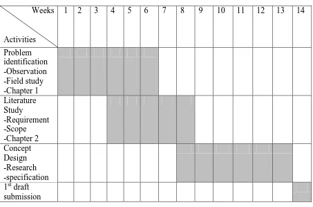
1.4
PROJECT SCHEDULE
Weeks
Activities
1
2
3
4
5
6
7
8
9
10
11
12
13
14
Problem
identification
-Observation
-Field study
-Chapter 1
Literature
Study
-Requirement
-Scope
-Chapter 2
Concept
Design
-Research
-specification
1
stdraft
submission
Table 1.1 : Semester 1 PSM Gantt-chart
Weeks
Activities
1
2
3
4
5
6
7
8
9
10
11
12
13
14
Embodiment
Design
Detail Design
Analysis
Prototyping
Full thesis
submission
6
CHAPTER 2
LITERATURE REVIEW
2.1
HISTORY OF HUMAN POWERED VEHICLE
There was a debate on who was the first to invent the bicycle or human powered
vehicle. Cycling is a ‘verb’ describing a sport that using paddle to cycle the bicycle.
Back in 14
thcentury, pupil ofLeonardo da Vinci, GianGiacamoCaprottiwas said to be
the earliest inventor. There was a sketch founded a bicycle a-like. It is confirm that, the
sketch itself does not represent the real he was the first bicycle inventor. (Prof. Dr.
7
17-18
thcentury – in Germany, another ‘bicycle’ was founded. And this time, the
bicycle was wooden made. It’s called ‘Laufmachine’ in Germans, which means ‘the
running machine’ with no pedals and steering installed ( Hammer.M, 2005). In 1816 the
German re-design it as an improvement to the previous version. This time, a steer
system is attached at the front wheel. The inventor is believe named to be Karl von Drais
de Sauerbrun.
Pedal and steering technology, 18
thcentury – people learned from previous
invention. A Scottish, Kirkpatrick MacMillan introduced the more improved design of a
bicycle. He was watching the bicycle is moved by kicking their feet to the ground. Then,
an idea was brilliantly came at the moment to invent something can move the bicycle
without kicking your feet. It was such a big impact on the current design of a bicycle. As
a blacksmith, MacMillan design the improvement. (Retrieved from Wikipedia “History
of Bicycle”)
Figure 2.1: no steering and pedal for the first bicycle founded also