ISSN: 1693-6930
accredited by DGHE (DIKTI), Decree No: 51/Dikti/Kep/2010 341
Numerical Design of Ultra-Wideband Printed Antenna
for Surface Penetrating Radar Application
Roy B. V. B. Simorangkir*1, Achmad Munir2 1
Electrical Engineering Department, Institut Teknologi Harapan Bangsa
Jalan Dipatiukur No. 80-84, Bandung 40132, Indonesia, Ph./Fax: +6222-2506636/2507901
2
Radio Telecommunication and Microwave Laboratory
School of Electrical Engineering and Informatics, Institut Teknologi Bandung Jalan Ganesha No. 10, Bandung 40132, Indonesia, Ph./Fax: +6222-2501661/2534134
e-mail: [email protected]*1, [email protected]
Abstrak
Radar penembus permukaan (SPR, surface penetrating radar) adalah sebuah perangkat pencitra gelombang elektromagnetik yang bekerja dengan cara memancarkan dan mengirimkan pulsa periode sempit melalui antena. Karena penggunaan pulsa periode sempit, menurut dualitas transformasi Fourier, antena pita sangat lebar (UWB, ultra-wideband) menjadi salah satu kebutuhan penting dalam sistem SPR. Dalam makalah ini, sebuah antena cetak UWB yang baru diusulkan untuk digunakan pada aplikasi SPR. Pada dasarnya, antena usulan tersebut dikembangkan dari sebuah antena mikrostrip persegi dengan pencatuan berbentuk-T simetris. Beberapa metode investigasi seperti pembebanan resistif, transisi mendadak, dan modifikasi ground plane dilakukan untuk mencapai karakteristik lebar pita, efisiensi radiasi, dan ukuran yang diperlukan oleh sistem. Untuk mendapatkan desain yang optimal, karakteristik-karakteristik antena usulan dipelajari secara numerik melalui parameter fisik antena. Dari hasil investigasi menunjukkan bahwa antena usulan yang diimplementasikan pada substrat Epoxy FR-4 dengan permitivitas 4,3 dan ketebalan 1,6mm memiliki ukuran yang kompak 72,8mm x 60,0mm dan lebar pita yang besar mulai 50MHz-5GHz yang cocok untuk aplikasi SPR.
Keywords: ground plane berbentuk U, pita sangat lebar, radar penembus permukaan, transisi mendadak
Abstract
Surface penetrating radar (SPR) is an imaging device of electromagnetic wave that works by emitting and transmitting a narrow period pulse through the antenna. Due to the use of narrow period pulse, according to the Fourier transform duality, therefore ultra-wideband (UWB) antenna becomes one of the most important needs in SPR system. In this paper, a novel UWB printed antenna is proposed to be used for SPR application. Basically, the proposed antenna is developed from a rectangular microstrip antenna fed by symmetric T-shaped. Some investigation methods such as resistive loading, abrupt transition, and ground plane modification are attempted to achieve required characteristics of bandwidth, radiation efficiency, and compactness needed by the system. To obtain the optimum design, the characteristics of proposed antenna are numerically investigated through the physical parameters of antenna. It is shown that proposed antenna deployed on an FR-4 Epoxy substrate with permittivity of 4.3 and thickness of 1.6mm has a compact size of 72.8mm x 60.0mm and a large bandwidth of 50MHz-5GHz which is suitable for SPR application.
Keywords: surface penetrating radar, ultra-wideband, abrupt transition, U-shaped ground plane
1. Introduction
correspondence with a very wideband signal in frequency domain. Therefore, the antenna that has the ability to cover wide band of frequency range signals becomes one of the most important things needs in SPR system.
Unfortunately, the selection of center frequency and operating frequency range of SPR system which has to be accomplished by the antenna is a critical problem that needs more attention particularly in the design process. The center frequency determines the application of SPR, whilst the operation frequency range or bandwidth plays an important role in the resolution of SPR. The low operation frequency will result the deeper penetration level of SPR or vice versa, hence, the larger bandwidth of SPR the better resolution is produced. In addition, the larger bandwidth can also reduce late-time ringing which is happened as multiple reflections between antenna open ends and the feed point. The ringing will cover the next pulse reflection from the observed object as it appears at the tail pulse that will affect the masking of the target and automatically worsens the imaging quality of the system.
In this paper, a compact novel UWB printed antenna works for a frequency range of 50MHz-5GHz is proposed to be applied for SPR application. The frequency range is chosen as a tradeoff of between the resolution and the depth of penetration. The proposed antenna is developed from a rectangular microstrip antenna fed by symmetric T-shaped [6]. Some methods such as resistive-loaded, abrupt transition and ground plane modification are included in the development to achieve the required specifications [7]-[11]. The development is done by adding four abrupt transitions on its T-shaped arm, a circular patch under it, and U-shape ground plane on the other side of the antenna. Each resistive load at the end of its arms as well as the modification of ground plane shape is applied to improve impedance matching throughout the required frequency region so the requirement of proposed bandwidth could be achieved. Four abrupt transitions and additional circular patch are needed to improve the radiation efficiency of antenna as well. The numerical design is performed to find the optimum design of antenna where physical parameters of antenna such as length and width of arms, length and width of ground plane, transition angle, radius of circular patch, resistive load value, and thickness of substrate is investigated intensively through its parametrical study.
2. Numerical Design
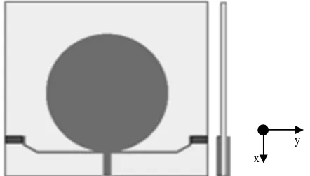
Based on simplicity reasons and possibility of further development, a resistive loaded T-shaped monopole antenna is chosen as an initial design of the proposed antenna. Some physical parameter investigations such as additional abrupt transitions to the arms, placement of circular patch, and ground plane modification are implemented to the existing design to accomplish the optimum design. Figure 1 illustrates a shape of the proposed antenna for investigations which consists of three main parts: (i) arms of antenna, (ii) circular patch, and (iii) U-shaped ground plane.
Figure 1. Shape of proposed antenna for investigations
2.1. Arms of Antenna
Basically, arms of the proposed antenna are modified from arms of resistive-loaded shaped monopole antenna by applying abrupt transitions on its shape. Here, the length of
shaped monopole antenna is 62mm which is determined from a half wavelength of required bandwidth at the center frequency. As the resistive loading is the most-widely used method to enhance the antenna bandwidth which still maintains the compactness of the antenna [7]-[9], the method is also applied in the design to satisfy the bandwidth and dimension specification as well. The initial value of resistive loading at the end of arms is 100Ω. However, since the method decreases the radiation efficiency, abrupt transition method by applying a number of sharp edges at the arms is employed for compensation [7]. Hence, the antenna radiation at the edge of transitions is more effective as the increase of displacement current. In the numerical design, the number of abrupt transition is taken to be four for simplicity and compactness reason.
2.2. Circular Patch
As the next step, a placement of circular patch upper the arms of antenna is investigated. The initial value of patch radius for the investigation is chosen to be 22mm as this value is close to quarter wavelength of the center frequency. Since the effect of resistive loading in the previous step contributes the decrease of radiation efficiency stronger than of the abrupt transitions, the placement of circular patch is expected able to improve the radiation efficiency. In addition, the additional circular patch also affects to the increase of radiation resistance and the effective aperture of antenna as well, therefore the radiation efficiency of antenna can increase accordingly. However as the increase of radiation resistance of antenna, the total impedance will change to be unmatched that needs to be improved.
2.3. U-shaped Ground Plane
The next step in numerical design of UWB printed antenna is modification of the ground plane. As the method has been applied to improve the impedance matching of antenna [10]-[11], in the design the original ground plane is then modified in order to drawback the matching impedance which has been disturbed by additional circular patch in the previous attempt. Hence, the final geometry of the proposed antenna is shown in Figure 2. The optimum parameters of proposed antenna such as length of arms (A), transition angle (B), length of arms after transition (C), width of arms (D), position of arms from ground plane (E), length and width of ground plane (F, G), radius of circular patch (R), resistive loading value, and thickness of substrate are investigated through parametrical studies with the reflection coefficient (S11) is used for the performance indicator for each parameter.
(a) front view (b) back view
Figure 2. The proposed antenna and its parameters, (a) front view, (b) back view.
performing the parametrical study to obtain the optimum value of F. With the obtained optimum value of F, the parametrical study is conducted again to obtain the optimum value of G. Figures 3 and 4 show the effect of varying parameter F and G to the reflection coefficient (S11), respectively. From the result, the optimum value of F is 60mm, whilst for G is 15mm. It is shown that the adjustment of F influences significantly to the improvement of impedance matching for high frequency (> 1250MHz) and the low frequency (50MHz–600MHz), whereas the adjustment of G plays an important role to the improvement of impedance matching for pass band (600MHz–1250MHz).
Figure 3. Effect of varying length of U-shape ground plane (F) to reflection coefficient (S11)
Figure 4. Effect of varying width of U-shape ground plane (G) to reflection coefficient (S11)
By using the dimensions of U-shaped ground plane which have been obtained above, the dimensions of arms are then investigated numerically. The next tuning parameter is the length of arms (A). Figure 5 shows the effect of varying parameter A. The decrease of parameter A decreases consequently the bandwidth of proposed antenna. Here, the length of arms is chosen to be 50mm since the length gives a better performance in reflection coefficient (S11) and still provides sufficient total space of 62mm to make four abrupt transitions.
Figure 5. Effect of varying length of arms (A) to reflection coefficient (S11)
Figure 7. Effect of varying length of arms after transition (C) to reflection coefficient (S11)
Figure 8. Effect of varying width of arms (D) to reflection coefficient (S11)
Figure 9. Effect of varying position of arms from ground plane (E) to reflection coefficient
(S11)
Figure 10. Effect of varying radius of circular patch (R) to reflection coefficient (S11)
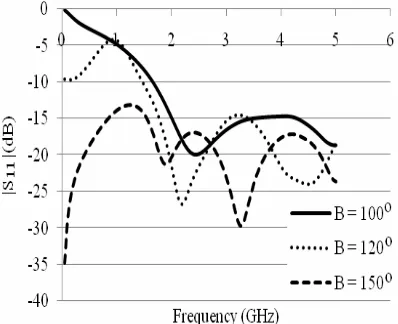
Figures 6 and 7 plot the effect of varying transition angle (B) and length of arms after transition (C) to the reflection coefficient (S11), respectively. From the results depicted in Figure 6, it is noted that the wider angle of transition the wider bandwidth is obtained. However, here the transition angle is chosen to be 1500 due to the compactness reason as the wider transition angle the larger dimension of antenna is required. After obtaining parameter B, the adjustment of parameter C is then conducted numerically. In Figure 7, it is shown that the parameter C of 2mm gives the best performance to the reflection coefficient (S11). The shape of vertical straight of C after abrupt transition was chosen for simplicity reason.
Next, the investigation is then moved to the influence of varying width of arms (D) to the reflection coefficient (S11). Since each arm comes from the rectangular patch antenna, it can be analyzed with transmission lines approach for microstrip antenna. Hence, according to the equation in [12]which is usedto obtain the impedance of microstrip antenna, it can be noted that the impedance of microstrip antenna is affected by its thickness. Therefore, theoretically the changes on parameter D will affect the value of reflection coefficient (S11). From the result depicted in Figure 8, it can be seen that the parameter D influences the performance of S11 especially in high frequency region. Based on the investigation result, the parameter D is taken to be 1mm.
respectively. From the result in Figure 9, it is shown that the optimum performance is achieved when position of antenna arms is 0.5mm from the top edge of ground plane. The condition when the bottom edge of antenna arms coincides with the top edge of ground plane is used as the reference point. When the bottom edge of arms is placed higher than reference point, the parameter E is represented by positive value, otherwise it is represented by negative value. Whereas from Figure 10, although the change of parameter R gives no significantly effect to the change of S11, the radius of 22mm is chosen as it still demonstrates the best performance compare to others.
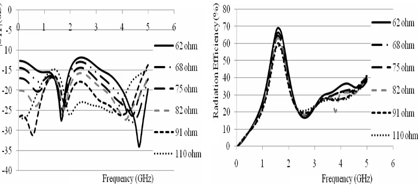
After completing investigations of physical parameters of antenna, the parametrical study of resistive loading value is performed. Figure 11 shows the effect of varying resistance value to the reflection coefficient (S11). It is shown that increase of resistance value affects to the increase of impedance matching performance indicated by the lower value of S11. However, the increase of impedance matching performance should be paid by the decrease of radiation efficiency as shown in Figure 12. Therefore, by considering the tradeoff between impedance matching of antenna and the radiation efficiency, the resistive loading of 82Ω is then taken for the design. This value is sufficient to accomplish the required bandwidth by still maintaining the radiation efficiency.
Figure 11. Effect of varying resistance value to reflection coefficient (S11)
Figure 12. Effect of varying resistance value to radiation efficiency
As the final step, the substrate thickness of FR-4 epoxy is investigated. Since the proposed antenna is deployed on the dielectric substrate, its thickness has a significant role as it will determine the Q factor. Figure 13 shows the influence of substrate thickness to the reflection coefficient (S11). From the result, it shows that the increase of thickness affects to the increase of working bandwidth. It can be noted that the thicker substrate thickness the low Q factor is obtained as the more energy is kept by the substrate. However, due to the availability of substrate and the result of performance, the thickness is chosen to be 1.6mm.
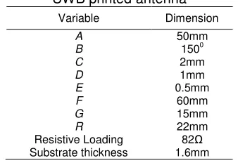
Table 1. Optimum dimensions of proposed UWB printed antenna
Variable Dimension
A 50mm
B 1500
C 2mm
D 1mm
E 0.5mm
F 60mm
G 15mm
R 22mm Resistive Loading 82Ω Substrate thickness 1.6mm
Figure 13. Effect of varying substrate thickness to reflection coefficient (S11)
From Figure 14, it is seen that for all ranges of desired frequencies, VSWR values are less than 1.5. This means that the proposed antenna can satisfy the requirements needed by the SPR system. The overall gain of proposed antenna as depicted in Figure 15 is quite low especially in low frequency region where the value is almost affected by the use of resistive loading as compensation to the impedance matching. However, as the resistive loading method is very effective to achieve wide bandwidth which is needed in SPR application, the gain quality needs to be sacrificed. In addition, the gain of antenna is actually one of far field parameters which is not the focus in SPR system that generally works on near and middle field. However, if the SPR system will be applied to detect the objects at far field region of the antenna, then the low gain can be compensated by increasing the input power of antenna or the antenna can be configured as an array of antenna.
Figure 14. VSWR of proposed UWB printed antenna with optimum dimensions
Figure 15. Overall gain of proposed UWB printed antenna with optimum dimensions
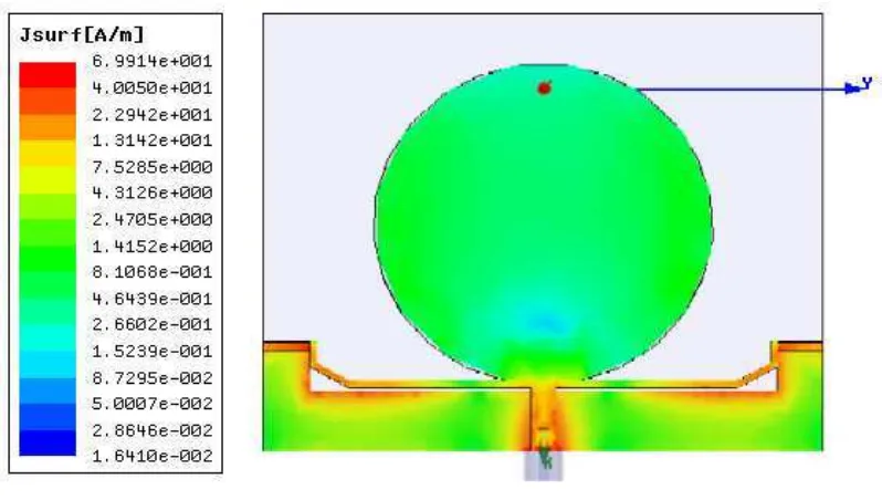
Whilst from Figure 17, it can be observed that at operating frequency of 2.55GHz, the currents propagate on the arms of antenna, the edge of U-sahped ground plane closed to the arms and resistive loadings. These confirm that the operating frequency of 2.55GHz is obtained from the appropriate length of antenna arms with the coupling interaction from the ground plane, and that the resistive loadings play an important role to match the impedance by absorbing the current or radiated energy, although, resulting the gain and radiation efficieny to be worsen.
(a) E-plane (b) H-plane
Figure 16. Normalized radiation pattern of proposed UWB printed antenna with optimum dimensions, (a) E-plane, (b) H-plane
f = 0.8 GHz
f = 2.0 GHz
f = 3.0 GHz
f = 4.0 GHz f = 5.0 GHz
f = 3.5 GHz
f = 2.55 GHz
f = 1.5 GHz f = 0.8 GHz
f = 2.0 GHz
f = 3.0 GHz
f = 4.0 GHz f = 5.0 GHz
f = 3.5 GHz
f = 2.55 GHz
Figure 17. Current distribution on surface of proposed UWB printed antenna at operating frequency of 2.55GHz
4. Conclusion
The numerical design of a novel UWB printed antenna proposed for SPR application has been demonstrated through its physical parameter investigation. The antenna that has a compact size of 72.8mm x 60.0mm has been implemented on an FR-4 Epoxy substrate with permittivity of 4.3 and thickness of 1.6mm. It is shown that each part of the proposed antenna, e.g. arms of antenna, circular patch, and U-shaped ground plane, has its respective role in establishing overall performance of antenna. Several parametrical studies such as transition angle, resistive loading, abrupt transition, and ground plane modification have been attempted to achieve the specifications. From the investigation results, it has been shown that the antenna has a large working bandwidth from 50MHz-5GHz for the VSWR value less than 1.5. It should be noted that the proposed antenna can accomplish the requirement need by the SPR system. Furthermore, more realistic investigation in the characterization of a manufactured compact UWB printed antenna is underway where more reliable properties will be demonstrated later.
Acknowledgement
This work is partially supported by the Program of Research and Innovation Research Group Grant 2011, Institut Teknologi Bandung (Program Riset dan Inovasi KK ITB 2011) Contract No. 144/K.01.6/DN/2011.
References
[1] Jol HM, Dechaine RJ, Eisenman R. Archeological GPR Investigation at Rennes-le-Chateau, France. Proceeding of 9th International Conference on Ground Penetrating Radar (GPR). Santa Barbara. 2002; 91-95.
[2] Daniel DJ. Ground Penetrating Radar. Second Edition. London: IEE Radar, Sonar, Navigation and Avionics Series. 2004.
[3] Ishikawa J, Kiyota M, Furata K. Test and Evaluation of Anti-personnel Landmine Detection Based on Vehicle-mounted GPR System. Japan Science and Technology Agency. IEICE Technical Report No. 105(363). 2005
[4] Machguth H, Eisen O, Paul F. Helicopter Borne Snow Profiling on Alpine Glaciers with GPR.
[5] Kenneth RM. Use of GPR for Rehabilitation of Composite Pavements on High Volume Roads.
Transportation Research Record: Journal of the Transportation Research Board. 2002; 1808(14): 122-126.
[6] Menon SK, Lethakumary B, VasudevanK, Mohanan P. Wide Band Rectangular Microstrip Antenna Using Symmetric T-shaped Feed. Microwave and Optical Technology Letters. 2002: 35(3). 235-236.
[7] Wu T, King R. The Cylindrical Antenna with Nonreflecting Resistive Loading. IEEE Transactions on Antennas Propagation. 1965; 13(3): 369-373.
[8] Shlager KL, Smith GS, Maloney JG. Optimization of Bow-tie Antennas for Pulse Radiation. IEEE Transactions on Antennas Propagation. 1994; 42(7): 975–982.
[9] Wong KL, Lin YF. Small Broadband Rectangular Microstrip Antenna with Chip-resistor Loading.
Electronics Letters. 1997; 33: 1593-1594.
[10] Prombutr N, Kirawanich P, Akkaraekthalin P. Bandwidth Enhancement of UWB Microstrip Antenna with a Modified Ground Plane. International Journal of Microwave Science and Technology. 2009.
[11] Wang F, Du Z, Wang Q, Gong K. Enhanced-bandwidth PIFA with T-shaped Ground Plane.
Electronics Letters. 2004; 40: 1504-1505.