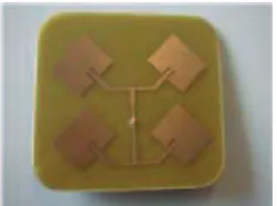
ISSN: 2180 - 1843 Vol. 3 No. 1 January - June 2011 15 Abstract
This paper present the designs of array antenna from type of inset-fed microstrip patch antenna by using single port oriented at 45° and -45°. The antennas are capable to generate dual-polarization radiation patern centered at 45° and -45°. Combinations of two patches using quarter-wave impedance matching technique has been used to designs the array antennas operate at 2.4 GHz. The designs are simulated using Microwave Oice 2004 and were fabricated on FR4 substrate with a dielectric constant εr =4.7, tan δ =0.019 and thickness
=1.6mm. The simulation and measurement result have been compared. The 3 design 1x2 array antennas yield a bandwidth greater than 5%. The gain of the proposed antennas is also stable with operated frequency. The result showed that the combination of more patches in array can improve the return loss and gain performances.
Keywords: Dual polarized, inset feed, microstrip antenna, patch antenna.
I. INTRODUCTION
IN various application of dual polarization antenna, the microstrip antenna element
has ofers three excellent advantages
relative to other types of antennas
[5]-[7]; low weight, low proile with conformability and low manufacturing
cost. Recently, in many wireless communication and radar system, a dual
polarized is greatly desired. In practices,
a dual-polarized microstrip antenna can
be realized by feeding the rectangular
DUal POlaRIzaTION SINgle PORT INSeT FeeD
MICROSTRIP PaTCh aRRay aNTeNNa
M.z.a. abd aziz
1, M.S.R. Mohd Shah
1, M.K. Suaidi
1, M.K.a. Rahim
21
Faculty of Electronic and Computer Engineering,
Universiti Teknikal Malaysia Melaka,
Hang Tuah Jaya, 76100 Durian Tunggal, Melaka Malaysia
2
Faculty of Electrical Engineering, Universiti Teknologi Malaysia,
81310 Skudai, Johor, Malaysia
Email: [email protected], [email protected],
[email protected]
microstrip patch at two orthogonal edges, through edge feed or probe feed, which excites TM01-and TM10-mode with orthogonal polarizations [1]–[4]. Both the element itself and its array oten achieve isolation of about -20dB [1]–[3].The most reported technique for achieving dual polarization is using diferent feed mechanisms such as aperture-coupling a single patch with crossed narrow slots or two ofset narrow slots [5]. This technique
requires a relatively complicated feed
arrangement [6] or a complex multiplayer construction [7] to reduce the coupling
between the two feed lines and therefore
adds complexity to the fabrication
process.
In this leter, the design of inset fed
microstrip antenna is proposed at 45° and -45° to achieve the optimum performance of the return loss, antenna
gains and polarization loss. A design of
the broadband dual-polarized microstrip
antennas is proposed by using the
simply inset feed technique but slant at desired rotation. In most applications, the
requirement of propagation can be met with a single patch structure. However,
in some cases, sharp beamwidth was
required, as well as maintaining a low proile structure, which arise the
development of microstrip patch array
antennas. Both design of array antennas in this paper were connected using
parallel feed quarter-wave transformer
ISSN: 2180 - 1843 Vol. 3 No. 1 January - June 2011
16
II. DeSIgN PROCeDURe
Corresponding to the optimum design,
an antenna has been fabricated and
tested. Details of the antenna design and
its measured performance are presented and discussed. There were several ways
to design microstrip antennas such as transmission line, inset fed, proximity and aperture models. Details of the designed
broadband dual-polarized microstrip
antennas is proposed by using the inset
feed technique [9].The parametric study
on the single patch antenna is done irst
to understand the characteristics of the
antenna. Fig. 1 and Fig. 2 showed the dimension of the 45° and -45° single patch
antennas.
ε δ
IN
Fig. 1: Layout of the 45° polarized patch
antenna
Fig. 2: Layout of the -45° polarized patch
antenna
This paper is focusing on the combination of the same antenna to obtain a beter response by developing the arrays. For
this project, a parallel or corporate feed
coniguration was used to build up the
array. In parallel feed, the patch elements
were fed in parallel by using transmission
lines. The transmission lines were divided
into two branches according to the
number of patch elements. The
quarter-wave transformer impedance matching
technique was applied to divide the power equally to all patches.
The impedances of the line were
translated into length and width by using Microwave Oice 2006. Figure 3 show the circuit layout of 1x2 array antennas. This design can produce beter high gain and broadband compared single element. The
position of the patch antenna is oriented at 45° and -45° to obtain dual- polarized radiation.
The design of 2x2 and 1x4 and 2x4 array antennas also has been investigated. In both design, the improvement of return loss, VSWR, and antenna gain was investigated. The feeding type of 2x2 and 2x4 array antenna is using coax probe. Whereas, the 1x2 and 1x4 array antenna are using quarter wavelength transmission line feeding technique.
Fig. 3: Fabrication design of 1x2 array antenna
Fig. 4: Fabrication design of 1x4 array antenna
ISSN: 2180 - 1843 Vol. 3 No. 1 January - June 2011 17 . 6: Fabrication design of 2x4 array antenn
Fig. 6: Fabrication design of 2x4 array antenna
III. SIMUlaTION
Once, all physical dimensions have been
calculated, the design would then be simulated by using Microwave Oice 2006 sotware to simulate the return loss, radiation patern, and VWSR of the
antenna. The simulation results for dual
polarized 1x2 array antennas were 1.376 and -17.66 dB for VSWR and return loss
respectively. While, the simulation result
for dual polarizations 1x4 array antennas were 1.370 and -22.33 dB. Fig. 7 and 8
shows that the combination results of
1x2, 1x4 and 2x2 array antennas. All
simulation data are tabulated in Table 1.
Again, this proves that the combination
of more patches in the array antenna can
improve the return loss and beter high gain performances.
Fig. 7: Return Loss [dB] for 1x2 and 1x4
Fig. 8: Return Loss [dB] for 2x2 array antenna
Table 1 show the simulation result for basic antenna parameters of dual
polarized antenna design. All dual polarized antenna have been design at
2.4 GHz resonant frequency and return
loss lower than – 10 dB for 90% radiation eiciency. The return loss and bandwidth
of dual polarized antenna was improved when more patch element is used.
Table 1: Simulation result for dual polarized array antenna
Dual Polarized Antenna Array 1 x 2 1 x 4 2 x 2 2x4
Resonant Freq
(GHz) 2.4 2.4 2.4 2.4
Return loss
(dB) -17.60 -21.08 -19.4 -32.34
VSWR 1.35 1.37 1.24 1.41
BW (%) 4.42 4.41 5.46 7.08
Fig. 9 (a) had shown the combination of radiation patern simulation result for 45°and -45° polarizations 1x2 and 1x4 array antennas, respectively. Fig. 9 (b) show the simulation results for 45° and -45° dual-polarized 2x2 array antennas radiation patern at the resonant
frequency.
(a)
(b)
IV. MeaSUReMeNT ReSUlTS
The same parameters involve in the
simulation were measured using Advantest R3767 CG Network Analyzer. The return loss is below -10 dB within the frequency range between 2.4-2.61 GHz, corresponding to a bandwidth of 4.22%.
For the measurement setup of radiation
patern, the reference of transmiter is using monopole antenna. Figure 10 and 11 shows the radiation patern measurement
for 45° and -45° polarized patch antenna respectively. In this condition, the two planes are considered here at an element plane location 45° and -45°. The element
plane designates E-plane for location
45° and H-plane for location -45°. The cross-polarization for both elements is perpendicular to the others.
The 45° polarized patch antennas will
generate linear electromagnetic ield radiation with principle plane at angle 45°. Similarly, the linear electromagnetic ield radiation at principle plane of -45° is generated from -45° polarized antennas.
This principle plane can be seen from the
direction main lobe angle in radiation patern.
Fig. 10: Radiation pattern for 450 polarized patch antenna
Fig. 10: Radiation patern for 45° polarized
patch antenna
Fig. 11: Radiation pattern for -450 polarized patch antenna
Fig. 11: Radiation patern for -45° polarized
patch antenna
Figure 12 and 13 shows the return loss
measurement result for dual polarized
antenna. The resonant frequency has shit for 0.04 GHz to 0.15 GHz at the let side. This may be due to dielectric permitivity
of the substrate is not uniform at 2 GHz frequency band. However, the return loss of the dual polarized antenna seems improved when more patch element is used.
ciple plane at angle at rized n
is used.
Fig. 12: Return Loss [dB] for 1x2 and 1x4 array.
a
Fig. 13: Return Loss [dB] for 2x2 array antenna.
Fig. 13: Return Loss [dB] for 2x2 array
antenna.
Figure 14 shows the radiation patern
measurement result for dual polarized antenna. The main lobe for all dual polarized antennas can be seen at 0°
ISSN: 2180 - 1843 Vol. 3 No. 1 January - June 2011 19 45°and -45°. When, more elements is
used, the directivity of the mutual main beam will also increase.
nna
ent has is may be at al
(a)
(a)
(b) (b)
(c) (c)
Fig. 14: (a) Measured radiation patern of 1x2 patch array antenna (b) Measured radiation
patern of 1x4 patch array antenna (c) Measured radiation patern of 2x4 patch array
antenna
However, the principle plane of 45° and
-45° lobes also exist at their respective
plane. So, the dual linear polarized is
exist and radiate from its respective patch element. The mutual coupling efect can be reduce by using greater spacing
between 45° patch elements and -45°patch elements.
The gain of the single element antenna almost 2.2 dB and the gain of 1x2 arrays is 2.9 dB. By designing more patch, which is 2x2 and 1x4 array antennas, the enhancement of gain is achieved were 3.1 dB and 4 dB, respectively.
Tables 2 show the comparison results between simulation and measurement.
This tables show the values were slightly diferent. However the antennas still
operate at resonant frequency around 2.4GHz with low VSWR. The VSWR and return loss have been observed for both
single and 1x2 patches array antenna.
Table 2: Comparison between simulation and measurement result for dual polarized array
antenna
Dual Polarized Array Antenna
1 x 2 1 x 4 2 x 2
Sim Meas Sim Meas Sim Meas Freq
(GHz) 2.4 2.54 2.4 2.51 2.4 2.48
RL (dB) -17.6 -17.3 -21.1 -18.2 -19.4 -21.3
VSWR 1.35 1.18 1.37 1.16 1.24 1.17
BW(%) 4.42 3.45 4.41 4.77 5.46 3.61
V. CONClUSION
It can be concluded that the responses
from the 1x4 patches were beter compared to the 1x2 array antenna and single patches antenna. Although the
results from the measurement were not
exactly same as in the simulation, it was still acceptable since the percentage error
ReFeReNCeS
[1] K. F. Lee and W. Chen, Eds., Advances
in Microstrip Antennas and Printed Antennas, New York: Wiley, 1997, pp.
163–217.
[2] J. R. James and P. S. Hall, “Handbook of Microstrip Antennas”, Eds., Peter
Peregrinus, U.K, 1989.
[3] L. J. Du Toit and J. H. Cloete, “Dual polarized linear microstrip patch array,” in
Proc. IEEE Antennas and Propagation Symp. Dig, 1987, pp.810–813.
[4] M. J. Cryan and P. S. Hall, “Integrated Active Antenna with Simultaneous Transmit-Receive Operation”Electron.
Let, vol. 32, no. 4, pp. 286–287, 1996.
[5] Padhi, S.K., Karmakar, N.C., Sr.,
Law, C.L., and Aditya, S. Sr., “A dual
polarized aperture coupled circular
patch antenna using a C-shaped
coupling slot”, IEEE Trans. Antennas
Propag., 2003, 51, (12), pp. 3295–3298.
[6] Lind mark, B., “A novel dual polarized
aperture coupled patch element with
a single layer feed network and high
isolation”. IEEE Antennas Propagation Society Int. Symp. Dig., Montreal, Que.,Canada, 1997, Vol. 4, pp. 2190– 2193.
[7] Shavit, R., Tzur, Y., and Spirtus, D, “Design of a new dual-frequency and
dual-polarization microstrip element”, IEEE Trans. Antennas Propag., 2003, 51,
(7), pp. 1443–1451.
[8] A. Adrian and D. H. Schaubert, “Dual
aperture-coupled microstrip antenna for dual or circular polarization”,”Electron.
Let., vol. 23, pp. 1226–1228,1987.
[9] M. S. R. Mohd Shah, M.R Che Rose,
M. F Abdul Kadir, D. Misman, M. Z.
A. Abdul Aziz, and M. K Suaidi, “Dual