ELECTROMAGNETIC POWER PLANT BASE ON PERENDEV CONCEPT
Nur-Ahmad Bin Mazlan
ELECTROMAGNETIC POWER PLANT BASE ON PERENDEV CONCEPT
NUR-AHMAD BIN MAZLAN
This Report Is Submitted In Partial Fulfillment of Requirements for the Degree of Bachelor in Electrical Engineering (Industrial Power)
Fakulti Kejuruteraan Elektrik Universiti Teknikal Malaysia Melaka
“I hereby declare that I have through this report entitle “Electromagnetic power plant base on perendev concept” and found that it has comply the partial fulfillment for awarding the degree
of Bachelor of Electrical Engineering (Industrial Power) ”
Signature : ………..
Supervisor‟s Name : PN. ELIA ERWANI BINTI HASSAN
“I hereby declared that this report is a result of my own work except for the excerpts that have been cited clearly in the references.”
Signature : ……….
Name : NUR-AHMAD BIN MAZLAN
Firstly, I would like to express my deep and sincere gratitude to ALLAH S.W.T for giving me the strength and ability to complete this project. I am deeply grateful to my supervisor, Pn. Elia Erwani Binti Hassan for his detailed and constructive comments. I owe my loving thanks to my parents and family. Without their capital, encouragement and understanding it would have been impossible for me to finish this FYP report.
Finally, I would like to thank to all my friends for their unwavering support in completion of this project and ONEMAGNET (M) SDN BHD. Without the support of those mentioned above, this completion would not have happened.
ABSTRACT
TABLE OF CONTENT
CHAPTER TITLE PAGE
ACKNOWLEDGEMENTS ii
ABSTRACT iii
LIST OF CONTENTS iv
LIST OF FIGURES vi
LIST OF TABLES viii
LIST OF ABBREVIATIONS ix
1 OBJECTIVE AND SCOPE 1
1.1 Introduction 1
1.2 Objective 2
1.3 Scope 2
1.4 Problem statement 2
2 LITERATURE REVIEW 3
2.1 Introduction 3
2.2 Magnet type 3
2.3 Similar project 8
2.4 Magnetic fields 11
3 METHODOLOGY 13
3.1 Introduction 13
3.1.1 Project explanation 13
3.1.2 Material suggestion 14
3.1.3 Model upgrade 15
3.1.4 Project progress 17
3.1.5 Implementation 18
3.1.6 Device operation 19
3.1.7 Component description 20
4 RESULT, ANALYSIS AND DISCUSSION 28
4.1 Introduction 28
4.2 Result 28
4.3 Analysis 28
4.3.1 Initial Problem 28
4.3.2 Solution 29
4.3.3 Problem after solve the initial problem 29
4.4 Discussion 30
5 CONCLUSION AND RECOMMENDATION 32
5.1 Conclusion 32
5.2 Recommendation 32
5.2.1 Draft of device with DC motor 33
5.2.2 Component adding 34
5.2.3 Device operation 34
5.2.4 Model of project 35
5.2.5 Suggestion 36
REFERENCE 37
LIST OF FIGURES
FIGURE TITLE PAGE
1.0 Arrangement of magnet by 60 1
1.1 3 slide of magnet for rotor and stator 1
2.0 Sample of NdFeB magnet 4
2.1 Sample Permanent - Ferrite Magnet 4
2.2 Sample of Plastic & Rubber Magnet 5
2.3 Sample of Alnico magnet 6
2.4 Sample of smco magnet 7
2.5 Roger Code model 9
2.6 Mark Olson‟s model 10
2.7 Xpenzif model 11
2.8 Magnetic-field 12
3.0 Xpenzif model 13
3.1 Polystyrene 14
3.2 Pure steel screw 14
3.3 Mini lamp (dynamo) 14
3.4 Ring rubber 14
3.5 LED 15
3.6 Switch 15
3.7 Material upgrade 16
3.8 Project progress 17
3.9 Custom magnet 18
3.10 Draft Of Project Model 19
3.11 Arrangement of magnet at rotor and stator 20
3.12a Cylindrical magnet 21
3.12b Wrapped magnet compare to custom magnet 21
3.13a Magnet wrapped with cable tube 21
3.14 Cable tube 22
3.15 Thin isolator coil 22
3.16 PVC Pipe 23
3.17 PVC Pipe holder and board 23
3.18 Cable 23
3.19 LED 24
3.20 Multimeter 24
3.21 Arrangement of magnet 26
3.22 Stator 26
3.23 Pipe holder and solvent cement 27
3.24 Thin isolator coil 27
4.0 Region of flux magnet 30 5.0 Draft of device with DC motor 33
5.1 DC motor 34
5.2 Limit switch 34
LIST OF TABLE
TABLE TITLE PAGE
LIST OF ABBREVIATIONS
LED Light Emitting Diod
V Voltage
A Ampere
DC Direct current
AC Alternating current
CHAPTER 1
OBJECTIVE AND SCOPE
1.1 Introduction
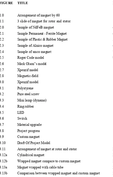
PERENDEV is a device that only use magnet force to make a continuously motion. The device have a 3 slide of magnet for rotor (as shown in figure 1.1), and a 3 slide of magnet for stator (as shown in figure 1.1). The magnet will arrange by angle 60° (as shown in figure 1.0). The device will continuously rotate when the rotor insert to the stator (as shown in figure 1.1).
Figure 1.0: Arrange magnet by 60
Figure 1.1 : 3 slide of magnet for rotor and stator stato
To make sure this device functional, the arrangement of magnet must be accurate. This device functional if it continuously rotate and this project is still under research & development
1.3 Objective
To design the model of perendev device by using autocad
To model the design into hardware and make sure it continuously rotate and have good enough force to rotate the mini dynamo.
1.3 Scope
The scope for this project is to build a mini model for perendev motor that use rare-earth permanent magnet and use only mini dynamo to produce the mili volt. This project will verify by using small load, such as LED, that connect to the output, where it can operate with small source.
1.4 Problem statement
CHAPTER 2
LITERATURE REVIEW
2.1 Introduction
Before start or modelling the project, the research about this project are explain as literature review. Below is the type of magnet, similar project and concept of magnetic field has explain.
2.2 Magnet type
Author: http://www.onemagnet.com/
Magnet has several types, in this chapter, 5 types of magnet will explain, the first types of magnet are:
NdFeB Rare Earth Magnet
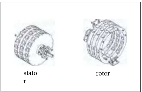
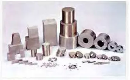
Figure 2.0 shown NdFeB, the third generation of rare-earth permanent magnet, has the high remanence, high coercive force, high-energy product and high performance/cost ratio, It is easily formed into various sizes and widely used in many fields such as aviation, electronics, instruments, meters, machine, medical instrument and the like. It is especially suitable for the development of high-performance, compact and light products. [3]
Permanent - Ferrite Magnet
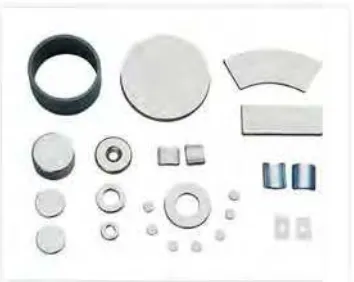
Figure 2.1 shown the Permanent-magnet iron oxide in made of SrO or Bao and Fe2O3 and is made by ceramic processing technology. Onemagnet have 6 models of Permanent-Magnet iron oxide products, namely Y10T, Y20, Y25,Y30,Y30BH, Y33, Y35 and etc, The products include rings, disks, blocks and segments. [3]
Figure 2.1 : Sample Permanent - Ferrite Magnet
Plastic & Rubber Magnet
Figure 2.2 shown Plastic & rubber magnets are made of bonded ferrite magnet powder, compound rubber and other materials. By extruding, rolling or injecting, the combination can be made into soft, plastic and flexible magnets with different shapes such as strip, coil, sheet, and other complicated shapes. They are widely used in micro motor, fridge, disinfecting cupboard, toy, stationery, ad, etc. [3]
Alnico
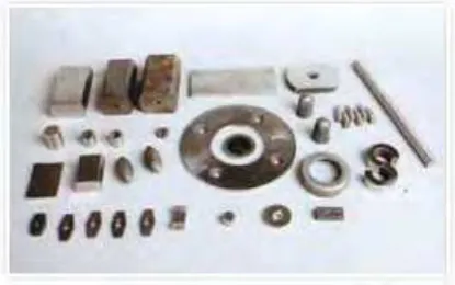
Figure 2.3 shown the alnico magnet. Alnico describes a family of materials, which is derived from a common base composition comprising of aluminum, nickel, cobalt and iron with varying additions of other elements. By varying the composition it is possible to tailor the magnetic properties to meet the needs of a wide variety of end use applications. There are two different manufacturing processes for Alnico : Cast Alnico can be made into many sizes and shapes, whereas Sintered Alnico is usually restricted to smaller sizes. However, both processes lead themselves to complex geometries and configurations. Standard Sintered Alnico has tighter dimensional tolerances due to its processing. It also has slightly lowest reversible temperature coefficient magnetism in permanent magnet materials have excellent working temperature up to 600, Alnico products are widely used in all kinds of meters and other applications. [3]
SmCo
Figure 2.4 shown Plastic & rubber magnets are made of bonded ferrite magnet powder, compound rubber and other materials. By extruding, rolling or injecting, the combination can be made into soft, plastic and flexible magnets with different shapes such as strip, coil, sheet, and other complicated shapes. They are widely used in micro motor, fridge, disinfecting cupboard, toy, stationery, ad, etc. [3]
2.3 Similar project
Author: http://www.fdp.nu/
Roger Code
Model by: Roger Cote
Stator and rotor material: wood
Stator magnet: Rare earth Permanent magnet Rotor magnet: Rare earth Permanent magnet Shaft: stainless steel
Explanation from Roger cote :
Figure 2.5 : Roger Code model
Mark Olson's
Model by : Mark Olson's Stator and rotor material: wood
Stator magnet: Rare earth Permanent magnet Rotor magnet: Rare earth Permanent magnet Shaft: Stainless steel
Explanation by Mark Olson's
Figure 2.6 Mark Olson‟s model
Xpenzif
Model by: Xpenzif
Stator and rotor material: Paper and perspec Stator magnet: none (use screw)
Rotor magnet: Rare earth Permanent magnet Shaft: Direct connected to bearing
Explanation by xpenzif
Figure 2.7 :Xpenzif model
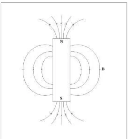
2.4 Magnetic fields
As early as 800B.c the Greeks discovered that certain kinds of stones exhibit a force that attracts pieces of iron. These stones are now called magnetite (Fe3O4) and the
phenomenon they exhibit is magnetism. In the thirteenth century, French scientists discover that, when a needle was place on the surface of a spherical natural magnet, the needle oriented itself along different directions for different location on the magnet. By mapping the direction taken by needle, it was determined that the magnetic force formed magnetic-field lines that encircled the sphere and appeared to pass through two points diametrically opposite each other. These point, called the north (N) and south (S) poles of the magnet, were found to exist for every magnet, regardless of its shape. The magnetic-field pattern of a bar magnet is displayed in figure 2.8. It was also observed that like poles of different magnet repel each other and unlike poles attract each other. This attraction-repulsion property is similar to the electric force between electric charges, except for one important different: can be isolated, but magnetic poles always exist in pair. If a permanent magnet is cut into small pieces, no matter how small each piece is, it will always have north and south pole. The magnetic lines