MODELING OF A GANTRY CRANE USING REAL TIME COMMAND SHAPING
SYAHIR BIN SAHIBULLAH ZAHIDI
This report is submitted in partial fulfillment of the requirements for the award of Bachelor of Electronic Engineering (Industrial Electronics) With Honours
Faculty of Electronic and Computer Engineering Universiti Teknikal Malaysia Melaka
UNIVERSTI TEKNIKAL MALAYSIA MELAKA
FAKULTI KEJURUTERAAN ELEKTRONIK DAN KEJURUTERAAN KOMPUTER BORANG PENGESAHAN STATUS LAPORAN
PROJEK SARJANA MUDA II
Tajuk Projek : Modeling Of A Gantry Crane Using Real Time Command Shaping
Sesi Pengajian : 2008/09
Saya SYAHIR BIN SAHIBULLAH ZAHIDI mengaku membenarkan Laporan Projek Sarjana Muda
ini disimpan di Perpustakaan dengan syarat-syarat kegunaan seperti berikut:
1. Laporan adalah hakmilik Universiti Teknikal Malaysia Melaka.
2. Perpustakaan dibenarkan membuat salinan untuk tujuan pengajian sahaja.
3. Perpustakaan dibenarkan membuat salinan laporan ini sebagai bahan pertukaran antara institusi
pengajian tinggi.
4. Sila tandakan ( √ ) :
SULIT*
(Mengandungi maklumat yang berdarjah keselamatan atau kepentingan Malaysia seperti yang termaktub di dalam AKTA RAHSIA RASMI 1972)
TERHAD*
(Mengandungi maklumat terhad yang telah ditentukan oleh organisasi/badan di mana penyelidikan dijalankan)
TIDAK TERHAD
Disahkan oleh:
___________________________________
(TANDATANGAN PENULIS) (COP DAN TANDATANGAN PENYELIA)
Alamat Tetap:
Lot 264, Kampung Kota,
Batu 4 1\2, Jalan Salor,
15100 Kota Bharu, Kelantan.
iii
“I hereby declare that this report is the result of my own work except for quotes as cited in the references.”
iv
“I hereby declare that I have read this report and in my opinion this report is sufficient in terms of the scope and quality for the award of Bachelor of Electronic Engineering
(Industrial Electronics) With Honours.”
Signature : ……….
Supervisor‟s Name : AZDIANA MD. YUSOP
v
vi
ACKNOWLEDGEMENT
Alhamdulillah, thanks to Allah for His divinity and blessing, I have completed my final year project for courses Bachelor of Electronic Engineering (Industrial Electronics)
successfully. I would like to thanks to my lovely family for their encouragement and
vii
ABSTRACT
viii
ABSTRAK
Kren digunakan secara meluasnya dalam pengangkutan dan pemindahan barang-barang berat dalam kilang, gudang, sektor pembinaan dan juga kemudahan nuklear. Terdapat 3 jenis sistem kren iaitu: kren gantry, kren rotary dan kren boom. Projek ini akan menumpukan perbincangan dan kajian dalam pengawalan kren gantry. SIMULINK telah dipilih dalam simulasi kren gantry untuk mengkaji sifat-sifat dinamik sistem kren
ix
TABLE OF CONTENTS
CHAPTER TITLE PAGE
PROJECT TITLE i
REPORT STATUS VERIFICATION FORM ii
STUDENT’S DECLARATION iii
SUPERVISOR’S DECLARATION iv
DEDICATION v
ACKNOWLEDGEMENT vi
ABSTRACT vii
ABSTRAK viii
TABLE OF CONTENTS ix
LIST OF TABLE xii
LIST OF FIGURES xiii
I INTRODUCTION
1.1 Overview 1
1.2 Project Objective 2
1.3 Problem Statement 2
1.4 Project Scope 3
1.5 Methodology 3
x
II LITERATURE REVIEW
2.1 Type of Crane 5
2.1.1 Gantry crane 6
2.1.1.1 Details about Gantry Crane 7
2.1.2 Tower Crane 8
2.1.3 Boom Crane 9
2.2 Crane Controller 10
2.2.1 Open Loop Techniques 10
2.2.2 Closed Loop Techniques 11
2.3 Command Shaping Control 12
2.4 Time Response 13
III RESEARCH METHODOLOGY
3.1 Real Time Command Shaping 17
3.2 PID Controller 19
3.2.1 Proportional Controller 21
3.2.2 Integral Controller 22
3.2.3 Derivative Controller 24
3.2.4 Tuning Parameter 25
3.3 Command shaping techniques 26
IV SIMULATION RESULT AND DISCUSSION
4.1 Simulation 28
4.1.1 Command Shaping Block System 29
4.1.2 Block Parameter 30
xi
4.3 Comparison with the Other Input for the Gantry
Crane Systems (Bang-Bang Input) 37
4.4 Command Shaping Input with feedback 42
4.5 Discussion 46
V HARDWARE INTERFACING
5.1 Introduction of Hardware Interfacing 47
5.2 Host PC and Target PC 48
5.3 RS-232 48
5.4 Data Acquisitions Card (DAQ card) 49
5.5 BNC-2110 50
5.5.1 Using the USER 1 and USER 2
BNC Connectors 52
5.6 RTW Setup 54
VI CONCLUSION AND RECOMMENDATION
6.1 Conclusion 58
6.2 Recommendation 59
REFERENCES 60
APPENDIX A 61
APPENDIX B 60
APPENDIX C 64
APPENDIX D 69
xii
LIST OF TABLE
NO TITLE PAGE
2.1 Evaluation of Rise time 16
3.1 Characteristic of P, I, and D (Effects of Increasing Parameters) 21
3.2 Tuning Parameters 25
4.1 Parameter value for position 35
4.2 Measured time of radian 36
4.3 Comparison input between shaped input and bang-bang input 39 4.4 Comparison parameter value (position) between command
shaping input and bang-bang input 40
4.5 Measured time of radian 41
4.6 Measured time of position 43
4.7 Measured time of radian 44
xiii
LIST OF FIGURES
NO TITLE PAGE
2.1 Gantry Crane 6
2.2 Illustration of a Gantry Crane 7
2.3 Rotary or Tower Crane 8
2.4 Boom Crane 9
2.5 Open-Loop Control Systems 10
2.6 Closed-Loop Control Systems 11
2.7 Multi pulse shaped input 13
2.8 Second-order underdamped responses for damping ratio
values 14
2.9 Underdamped Step responses 14
2.10 Normalized rise time versus damping ratio 16
3.1 Overhead gantry crane 18
3.2 Crane Response: Unshaped Command 18
3.3 Crane Responses: Shaped Command 19
3.4 The PID controllers block diagram 20
3.5 Plot of PV versus time, for three values of Kp (Ki and Kd held constant) 22 3.6 Plot of PV versus time, for three values of Ki (Kp and Kd held constant) 23 3.7 Plot of PV versus time, for three values of Kd (Kp and Ki held constant) 25
3.8 Generic Input Shaping Process 26
4.1 Simulation model in Matlab 29
xiv
4.3 Step function of step block 2 30
4.4 Pulse times for discrete impulse block 1 31
4.5 Pulse times for discrete impulse block 2 31
4.6 Functional block parameters for Nonlinear Model 32
4.7 Waveform for unshaped input 33
4.8 Waveform for input shaper 34
4.9 Waveform for summing both unshaped input and input shaper
(shaped input) 34
4.10 Simulation result for position of the trolley using command
shaping input 35
4.11 Simulation result for Swing Angle (radian) using command
shaping input 36
4.12 Simulation using bang-bang force input 37
4.13 Generation of Bang – bang Input Force 38
4.14 Parameter of the Bang – bang Input 38
4.15 Bang-bang input 39
4.16 Trolley position for bang–bang input 40
4.17 Swing angle for bang–bang input 41
4.18 Simulation model in Matlab 42
4.19 Simulation result for position of the trolley using PID controller 43 4.20 Simulation result for swing angle (radian) using PID controller 44
5.1 Experimental setup of gantry crane system 47
5.2 Simulink & xPC target 48
5.3 Connection pin of RS-232 49
5.4 Installation DAQ Card 50
5.5 BNC-2110 51
5.6 BNC-2110 front panel 52
5.7 USER 1 and USER 2 BNC connections 53
5.8 Connecting PFI 8 to USER 2 BNC 53
5.9 Solver Configuration Parameter 54
xv
5.11 System target file browser 55
5.12 Real Time Application task pane 56
5.13 Error Notification 56
CHAPTER I
INTRODUCTION
1.1 Overview
Cranes are widely used for transportation of heavy material in factories, warehouse, shipping yards, building construction and nuclear facilities. In order to lift heavy payloads in factories, in building construction, on ships and etc, cranes usually have very strong structures.
Crane system is tends to be highly flexible in nature, generally responding to commanded motion with oscillations of the payload and hook. The response of this system to external disturbances such as wind is also oscillatory in nature. The swaying phenomenon introduce not only reduce the efficiency of the crane, but also cause safety problem in the complicated working environment.
2
1.2 Project Objective
The objective of this project is to apply the technique using real time command shaping to extend the field of system by developing a systematic methodology to control and minimize residual vibration in systems.
1.3 Problem Statement
To move the payload using the crane is not an easy task especially when strict specifications on the swing angle and on the transfer time need to be satisfied. The fundamental motions of a gantry crane consist of travelling, load hoisting and load lowering. When the gantry crane start or finished the operation, it will give the undesirable result where it is swinging and vibration to the suspended load. Vibration control is an important consideration for rapid repositioning of flexible payloads. The large accelerations and speed needed to move a payload quickly can cause vibration, reducing the throughput of the overall process.
The gantry cranes are highly flexible, responding in an oscillatory manner to external disturbances and motion of the bridge and trolley. Payload oscillation has adverse consequences. Swinging of the hook makes positioning difficult and inefficient. When the payload or surrounding obstacles are of a hazardous or fragile nature, the oscillations present a safety hazard as well.
3
1.4 Project Scope
The scopes of this project are:
1) Study the model of a gantry crane system.
2) Research and study about command shaping technique.
3) Study on real time command shaping to get the output for gantry crane system. 4) Simulate and investigate the dynamic performance of the gantry crane system. 5) Learn more specific about Simulink in the MATLAB.
6) Get some examples for command shaping by using Simulink in MATLAB and then to study how does the command shaping work in the system.
7) Apply the technique to the gantry crane, testing and troubleshooting. 8) Project report write-up.
1.5 Methodology Study the basic concept
of gantry crane
Study and do research about command shaping
Make the simulation using Matlab
Analyze the simulation based on controller
Simulation result
Ok
4
1.6 Thesis Outline
This thesis describes the command shaping technique and how to apply this technique onto the gantry crane system. This thesis has six chapters. The first chapter will be describe about a brief introduction about the project consist the overview, objective, problem statement and scope of the project. A literature review of recent work on command shaping theory and application is presented in chapter 2. Other than that, the bang – bang control will addition to discussed and compared to command shaping. Chapter 3 describe about real time command shaping technique and illumination about PID controller. The simulation result and discussion about command shaping will be showed and discuss in chapter 4. Chapter 5 introduce detailed about hardware interfacing between hardware and simulation. And finally, chapter 6 summarizes the contributions of this work along with suggesting avenue for future explorations.
Make the settlement of the simulation to model
Generate and compile simulation model
Interface with Matlab
CHAPTER II
LITERATURE REVIEW
This chapter consists of some information about crane system and also an overview of the literature that has been published in relation to crane control.
2.1 Types of Crane
A crane consists of a hoisting mechanism such as hook and a support mechanism such as trolley girder. The hoisting mechanism has two main functions. It deposits the payload at the target destination and avoids the obstacle in the path by lifts and lowers the payload. The function of the support mechanism is moves the suspension point around the crane workspace.
Crane can be classified based on the degree of freedom the support mechanism offer the suspension point. There are 3 major types of crane system:
6
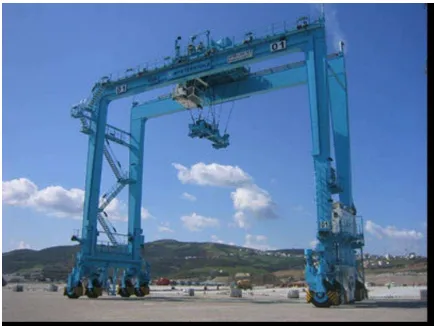
2.1.1 Gantry Crane
[image:21.612.113.548.213.539.2]Gantry crane is composed of a trolley moving in a girder along a single axis. In some gantry crane, the girder is mounted on the second set of orthogonal railings, adding another degree of freedom of the horizontal plane. Gantry crane is commonly used in factories, Figure 2.1.
7
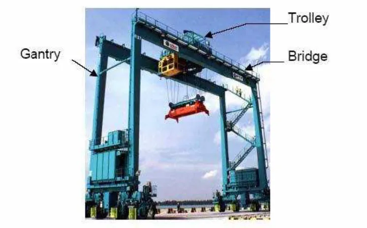
2.1.1.1 Details about Gantry Crane
[image:22.612.152.525.284.516.2]There are three main components in a gantry crane which are trolley, bridge and gantry. Figure 2.2 shows a typical gantry crane. Trolley with a movable or fixed hoisting mechanism is the load lifting component. It moves on and parallel to a bridge which is rigidly affixed to a supporting structure called gantry. The gantry extends downward from the bridge to the ground where it can be mobilized on wheels or set of tracks. The motion of the gantry on the ground, the trolley on the bridge and the hoisting of the payload provide the 3 degrees of freedom of the payload.
Figure 2.2 Illustration of a Gantry Crane
8
phenomenon introduce not only reduce the efficiency of the crane, but also cause safety problem in the complicated working environment.
This project will concentrate in controlling of gantry crane to reduce the vibration of the crane system.
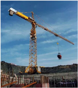
2.1.2 Tower Crane
[image:23.612.192.463.338.643.2]Tower crane is commonly used in construction, Figure 2.3. In this crane, the girder rotates in the horizontal plan about a fixed vertical axis. The trolley that holds the load can move in radial position over the girder. The load is attached to the trolley using a set of cables.
9
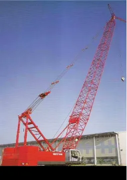
2.1.3 Boom Crane
[image:24.612.201.456.257.618.2]For the boom crane, a boom is attached to a rotating base. The rotational movement of the base along with the elevation movement of the boom places the boom tip over any point in the horizontal plane. The load hangs from the tip of the boom by a set of cables and pulleys. The radial and vertical positions of the load can be changed by changing the elevation angle of the boom. Boom cranes are very common on ships and in the harbors, Figure 2.4.