DOI: 10.12928/TELKOMNIKA.v14i3A.4381 152
Railway Signal Distributed Computer Control Switch
Module
Hualin Chen1,*, Lan Chen2 1
Electronic & Electrical Engineering, Wuhan Railway Vocational College of Technology, Wuhan, China
2
Wuhan Polytechnic, Wuhan, China
*Corresponding author, e-mail: [email protected]
Abstract
With the continuous miniaturization, electrical, high-speed and intelligent of railway signal equipment, the control switch module must have higher safety, reliability and anti-interference ability. Under this background, this paper studied the railway signal distributed computer control switch module. First of all, this paper introduced the main supporting technology of distributed interlocking system. These technologies mainly include solid state switch technology, fault tree analysis (FTA) technology, security and reliability design technology and so on. Then, this paper made clear the function requirement of the control switch module according to the characteristics of distributed computer interlocking system and the electrical characteristics of the circuit switch of the machine interface. Moreover, this paper made clear the design method of hardware circuit and software. In the aspect of hardware, this paper mainly analyzed the working principle of the switch control circuit, express acquisition circuit and the communication circuit. In the aspect of software design, this paper focused on the principle and work flow of the micro control unit (MCU) initialization, circuit control and the representation of information detection and so on. Finally, this paper used the fault tree analysis method to carry on the depth analysis of the security of the module. And the analysis results show that the railway signal distributed computer control switch module has a high reliability degree, safety degree and fault-Safety degree. At the same time, the module also meets the system's security index.
Keywords: distributed control, control switch module, security
Copyright © 2016 Universitas Ahmad Dahlan. All rights reserved.
1. Introduction
Railway signal is also known as the railway signal, and it is a technical means to control the train running intervals and ensure the safe operation of the train, and mainly includes three parts: signal, interlocking, block [1]. Among them, interlocking is a key link of railway signal, and its safety and reliability has always been the focus of research in all countries, and interlocking system is also the focus of the development of the railway industry. [2] Along with the development of technology and the maturity of experience, interlocking system is gradually developed by relay interlocking to electronic and distributed computer interlocking. At the same time, with the overall structure of the system changes, some of the implementation of the circuit is also towards a more compact, modular, intelligent direction [3]. Therefore, the research on the relevant execution units is a very important issue. As the switch control execution unit equipment, switch machine plays a vital role in the safe operation of trains. At present, the type of switch machine is fixed, but the control module switch all has their own characteristics. Based on this, a control switch module is studied based on the distributed computer interlocking system in this paper.
2. Research Contents
2.1. Related Technology of Controlling Switch Module
There are three main supporting technologies of distributed interlocking system. The main introduction is as follows.
(1) Solid state switch technology
following characteristics [4]: 1) it does not produce arc in operation and has high stability. 2) It can save design cost. 3) Solid state relays are small in size and more likely to be placed in PCB, making the product modular. 4) It can significantly improve the throughput of the data, and satisfy the requirement of the railway signal to the information transmission rate. 5) Compared with the electromagnetic relay, it has a longer service life. Therefore, the application of solid state switch instead of traditional relay will become a development trend.
(2) Fault tree analysis technique
As an important method of safety analysis, tree analysis fault is of great significance to analyze the safety of equipment and the factors that affect the safety of equipment. Fault analysis technology was developed by Baer laboratory in 1962 [5], which has the characteristics of clear cause and effect relationship, image and so on. It is mainly used in the following situations: 1) the top events in the analysis of the fault tree are the accidents that have occurred or the accidents can be expected. 2) to find out the inherent or potential risk factors in the system, and provide scientific and reasonable basis for the safety design, development of safety technology measures and safety management.
(3) Safety reliability design technology
Security refers to the ability of equipment accident, and it is an important indicator to determine the performance evaluation system, and it is also the most important characteristics of signal equipment. Reliability refers to the ability to work without fault, and it is also an important index to judge the performance of equipment. The application of safety and reliability technology in railway signal mainly include: fault-Safety Technology, error-avoiding technology and fault-tolerance technology.
2.2. Requirement Analysis of the Control Switch Module
Compared with the general equipment, in the life cycle of safety equipment, in addition to the need for functional requirements analysis of the system, it is necessary to carry out safety related analysis. This section will analyze the functional requirements and security requirements of the switch control module, and put forward the requirement for the software and hardware design of the following modules.
Analysis of switch machine interface requirements
Switch machine is switch control system of the implementing agencies, which is an important part of the computer interlocking system execution unit, and it is used for driving the switch and lock and to switch the location and status to reflect. Because it is directly related to the safety of the equipment, we should pay much attention to the performance and quality of the equipment. Its specific functions are as follows.
Conversion switch [6]: Switch machine must have enough power to drive the switch within the stipulated time to locate or reverse action according to the need.
Lock switch: When the switch conversion is completed, if the tongue rail and basic rail dense paste, switch machine should be the rail mechanical lock in the close state, to prevent the external force caused by the switch from of the basic track conditions.
Reflect the state of the switch: As a monitoring device switch, switch machine should ensure the correct reflection of the four states of turnout.
Module functional requirements analysis
Because the switch control circuit is a safe circuit, it must have a very high safety and reliability. When the fault occurs, it can timely alarm, and take appropriate measures to deal with security. So the switch control module of distributed computer interlocking should meet the following requirements [7]:
(1) It can complete the communication function with the interlocking host, and realize the security exchange of information with the communication extension, and it must use a secure communication protocol to ensure that the instructions are properly transmitted.
(2) The module can carry out self-inspection and fault location, and fault alarm for abnormal situation.
(3) The module can realize the position control and the counter position control function of the four wire switch.
(4) It must be able to capture the "position", "back" and "four open" in real time, and send the state information to the interlocking system.
Module security requirement analysis
railway signal equipment play an important role in the safety design of railway signal equipment. (1) Fault tree analysis method
Fault tree analysis (FTA) is an important safety analysis method, which can be applied to the whole design of safety related system [8]. It includes qualitative analysis and quantitative analysis. The process of qualitative analysis is the process of identifying faults and analyzing the faults. Fault tree quantitative analysis is the task of the fault tree will be built to quantify the quantitative analysis.
(2) Module hazard control
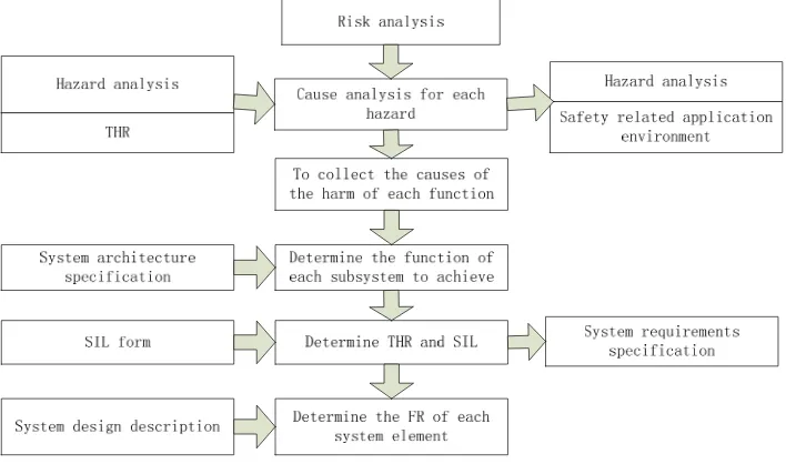
The control switch module is the key equipment to ensure the safe and efficient operation of the train, and its security requirements are very high, so it is very important to control the risk. By reference to the international general safety standard EN50129, this section will discuss the risk control of the switch control module through the safety analysis method, combining with the analysis and calculation. The risk control process is shown in figure 1.
Figure 1. Risk control process
(3) Module THR calculation
According to the requirements of the international standard EN50129, the safety integrity level of the safety integrity level of the switch risk of the train crash or crash accident may be 4, so we can come to the conclusion: THRswitch ≤ 10-9. According to experience, we assume that the maximum size of the system is about 150 sets of switches. The allowable risk rate for each set of switch control functions is THReach-set-points = 6.6×10⁻¹². We can assign THR once again. The THR is 4.2 ×10⁻¹² after the distribution of the switch, which is less than 6.6 × 10 -12
, and meets the requirements [9].
2.3. Hardware Design of Control Switch Module The overall structure of switch control module
According to the requirements of turnout module function demand and the requirements of switch machine interface in Section 2.2, combined with the related security technologies, we on the overall structure of the module hardware design. The hardware components of the module mainly include the data acquisition circuit, the switch control main circuit, and the logic control circuit, the current detection circuit, the microprocessor circuit and so on [10, 11].
alarm function; The signal circuit realizes the safety communication function between the switch module and the communication host computer.
Main circuit of switch control module (1) Switch control main circuit
Switch action circuit is mainly to complete the set operation and anti-exercise control of four wire direct current (DC) switch machine. Because it is directly related to the safety of the module control, the key design and analysis of the switch action circuit should be carried out. This paper selected the zero crossing trigger SCR type alternating current (AC) solid state relay, and the solid state relay that collects the signal representation of switch machine is FET device. Considering the Fault-Safety Principle, we choose the safety plate elastic load relay for control circuits and circuit safety switch.
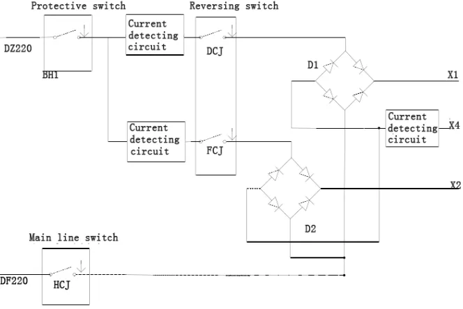
The circuit mainly includes switch control main circuit and current detecting circuit. Switch control main circuit to achieve the on-off control of fixed and reverse operating circuit. Current detection circuit is mainly to control the detection of the main loop current. Combined with the software design, we need to complete the monitoring of the state of the circuit and the fault conditions. Switch control main circuit is shown in Figure 2 below. It is mainly composed of switch DCJ, FCJ, HCJ, BHJ and the rectifier bridge D1, D2.
Figure 2. Hardware schematic diagram of switch control circuit
Current detecting circuit can realize the real-time monitoring of the switch machine operation circuit current information, and it also can complete the relay circuit component failure detection. In the main control circuit, we use the current detection circuit as the fault detector of the switch control circuit to meet the reactive fault-safety principle. AC detection circuit mainly completes the induction of line current, and the induction current is converted to the value that the processor can read, so as to realize the track monitoring and fault location function of the circuit. The safety supervision circuit mainly completes the supervision to the relay short circuit and the open circuit fault, realizes the real-time monitoring of the relay status, and ensures the timely detection of the circuit fault. Signal acquisition circuit mainly completes the acquisition of the state information of the switch and the back position, and it is mainly composed of a transformer, a resistor and a photoelectric coupler.
(2) Control circuit design
whole module. The circuit uses redundant MCU to control the circuit. The circuit is able to move only when two MCU execute the same command, and when two MCU receive command is not consistent or circuit failure; it needs to ensure that the switch will not miss the action. The controller area network (CAN) bus interface circuit is composed of 6N137 and TJA1050 devices. Compared with other communication bus, CAN bus have outstanding performance? Because the protocol meets the design requirements of the system, we choose CAN as the communication protocol between the module and the host. In order to improve the availability and reliability of the system, each module of the system is designed with double modules. A switch machine safety control is completed by two modules.
2.4. Software Design of Control Switch Module Software structure
The operation software of the control switch module is divided into the control software and the monitoring software. Control software is running in MCUA and MCUB much, and it is mainly responsible for the hardware control signal acquisition and logic processing and completes the control of switch machine. Control software program needs to carry out safety design. Monitoring software is non-security software, running in the monitoring of MCUC, and it mainly completes the monitoring of MCUA and MCUB status, and passes the information to the maintenance machine, it does not need to carry on the security design. The software adopts the structured design method, and the single task cycle operation mode is adopted. According to different functions, function module can be divided into the main program module, initialization module, synchronization information sending module, synchronization information receiving module, CAN communication processing module, information detection module and switch module action representation.
Main functions of control switch module (1) Main program module
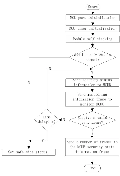
This module mainly realizes the operation function of each sub function module. After power up, it calls on the electric initialization module, and completes each register configuration and the system on the electric self-check function. After the check without fault, the module calls synchronous information processing module, and compares the MCUA data and MCUB data. If the synchronization information is consistent, the communication information processing module is called, and checks whether the control command is received. Then call the information detection module to analysis and process the results.
(2) Device initialization module
Figure 3. Total process of initialization module
(3) Synchronous information processing module
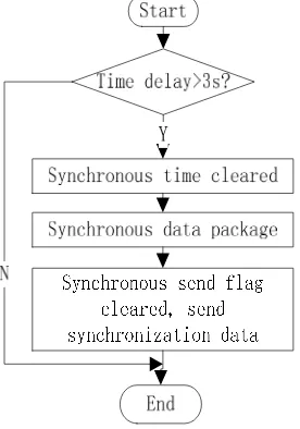
The synchronization information processing module is to improve the consistency of the output step of the double micro controller. It adopts the method of shaking hands with each other, and at the same time, it detects each other's handshake signal in the specified time. If the handshake is successful, the output will be synchronized with the operation or the counter command; Otherwise, it will continue to shake hands, and if synchronization is still not complete within the specified time period (1S), it is indicated a fault, which means that the system needs to alarm and complete the fault-Safety treatment. Synchronous message sending process is as shown in Figure 4.
(4) Control module
The control flow of turnout is introduced as follows: first of all, the module will resolve the valid control commands received, and determine whether the branch data of the dispatching branch is a symbol or a symbol of the turnout. And if it is, then the module is executed, or exit the module, then according to the effective switch control commands to achieve the switch machine set operation and inverse operation function.
(5) Representation information detection module
whether the switch is in the position, the reverse position, the four open, wiring errors, etc. In other cases, the fault alarm is carried out.
(6) CAN communication processing module
The module can realize the judgment function of the switch control command issued by the main engine, and it can realize the function of sending state information to the host machine. There is a CAN controller inside the AT90CAN128. Therefore, the software design mainly includes the initialization module of CAN controller, the data receiving module and the data transmission module. Its main program flow chart is shown in Figure 5.
Figure 4. Synchronous message sending flow chart
Figure 5. CAN communication main program flow chart
3. Results and Discussion
3.1. Calculation of Basic Failure Rate of Components
Table 1. The failure rate of the basic original
Components Working failure rate Components Working failure rate
Microprocessor 0.154 Solid state relay 0.067
Integrated operational amplifier 0.0433 Safety relay 0.167
CAN transceiver 0.0199 Reset button 0.0082
Oscillator 0.081 DC/DC 0.599
Voltage reference diode 0.22 Film resistor 0.000881
Switching diode 0.03 Weak electricity printing 0.0033
Electrical printed circuit board 0.00177 Circuit breaker 0.78
Using connectors 0.00178 Photoelectric coupler 0.0294
Wire wound resistor 0.0211 Transformer 0.639
Power winding resistance 0.0975 Precision wire wound potentiometer 0.9987
Chip capacitor 0.082 Solid tantalum capacitor 0.0043
Into the formula, the failure rate was 0.0296.
3.2. Security Analysis
(1) Security analysis of action circuit
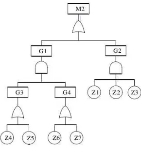
The fault tree method is used to further analyze the switch module action function fault. As a result of the "two take two" system architecture, it can be formed a fault tree of four wire switch mode operation circuit which is shown in Figure 6. And by analysis and calculation, the event risk of all events is shown in Table 2.
Figure 6. Fault tree of action circuit of four wire switch module
Table 2. Event hazard rate of switch module action circuit
Label Event Event hazard ratio /h Label Event Event hazard ratio /h
Z1 Reversing switch fault 3.27*10-16 G3 A path control output error 1.61*10-8
Z2 Loop total switch fault 1.79*10-8 Z6 Microcontroller B output error 6.56*10-9
Z3 Protection switch fault 2.2*10-7 Z7 Driver circuit B output error 8.81*10-9
G2 Switch fault 1.7*10-30 G4 B path control output error 1.61*10-8
Z4 Microcontroller A output
error 6.56*10
-9 G1 Control output error 2.32*10-16
Z5 Driver circuit A output error 8.81*10-9 M2 Switch module action function
fault 3.32*10
-16
As a result, we can get that the safety index of the action circuit is 2.31*10-16/h. And the value smaller than the THR distribution value 2*10-12 of the switch module action function fault in the text, so it satisfies the security index of the system.
(2) Safety analysis of the express circuit
of the switch is located in the "four open" position error collection. Event EB indicates that the error collecting of the switch in the "four open" position is the reverse position. Event EC indicates the error collecting of the switch in positioning is the reverse position, and the event ED indicates the error collecting of the switch in the reverse position is location. Through the analysis of the representation circuit, it is almost impossible for these four kinds of events, and it is smaller than the THR distribution value 10-12 of the position detection function of the switch module in the paper, and it meets the requirements of the system to the point of the signal acquisition function.
4. Conclusion
Through the analysis of the above results, we can find that the railway signal distributed computer control switch module has a high reliability degree, safety degree and fault-Safety degree. At the same time, the module also meets the system's security index.
References
[1] Wenzhen Kuang, Youjie Cao. The research of switch control module based on distributed computer interlocking system.Applied Mechanics and Materials. 2013; 433-435: 1452-1457.
[2] Hei X, Takahashi S, Nakamura H. Modeling and Analyzing Component-Based Distributed Railway Interlocking System with Petri Nets. IEEJ Transactions on Industry Applications. 2009; 129(5): 455-461.
[3] Liang L, Zhao F, Wang S. A Reliability Evaluation of High Speed Railway Traction Substation Based on the GO-FLOW Methodology. TELKOMNIKA Indonesian Journal of Electrical Engineering. 2014; 12(7): 4954-4962.
[4] Feng C, Yuan S, Guan H. Design and Implementation of NTY-I Computer Interlocking System. Urban Mass Transit. 2014: 10-17
[5] Yamamoto S, Schulze KL, Bellen HJ. Introduction to Notch signaling. Methods in Molecular Biology. 2014; 1187(1187): 1-14.
[6] Zou S. Signal Controlling Technology of Modern Tramcar. Railway Signaling & Communication. 2014: 12-19
[7] Yan X, Wu Q, Zhang C, Li W, Chen W, Luo W. An improved genetic algorithm and its application. TELKOMNIKA Indonesian Journal of Electrical Engineering. 2012; 10(5): 1081-1086.
[8] He Tao. Safety Analysis and Design for the Switch Control Unit of All-electronic Computer Interlocking System. TELKOMNIKA Indonesian Journal of Electrical Engineering. 2012; 10(5): 1057-1061.
[9] Chen G W, Yang J H, Zhang F. Application Research Based on Flex Ray Bus for All-Electronic Computer Interlocking System of Railway Signal. Advanced Materials Research. 2013; 671-674: 3179-3184.
[10] Tao H, Jianxin R. Research of Reliability, Availability and Maintainability on the All-electronic Computer Interlocking System. TELKOMNIKA Indonesian Journal of Electrical Engineering. 2014; 12(8): 5877-5885.