I
DEVELOPMENT OF DC VOLTAGE REGULATOR CIRCUIT FOR BIO-BATTERY CEL
MUDASSAR BASHIR
A thesis submitted
in partial fulfillment of the requirements for the degree of Bachelor of Electronic Telecommunication Engineering
Faculty of Electronic (Telecommunication Engineering)
IV
DEDICATION
V
ACKNOWLEDGEMENTS
I would like to express my sincere gratitude and appreciation to my supervisor, Dr.
Mohammad Saeed Jawad the valuable support, guidance and encouragement. He
provided me with an excellent research environment, left me enough freedom to do
things the way I thought they should be done, and was always available to edit my work.
His willingness to encourage me contributed tremendously to this project. Besides, I am
deeply and forever indebted to my parents, brother and sisters for their love, support and
encouragements throughout my entire life. Without helps of the particular that
mentioned above, I would not be successful and might face many difficulties while
doing this project.
I am forever indebted to my parents for their patience and understanding, alleviating my
family responsibilities and encouraging me to concentrate on my study.
Finally and most importantly, I would like to express special thanks to my wife for her
support when it was most required. Without her help and encouragement, this study
VI
ABSTRACT
VII
ABSTRAK
Voltan litar pengatur menggunakan dalam pelbagai peranti elektronik, mengawal selia pengatur voltan dc adalah perlu bagi peranti. Diod zener adalah sebaik-baik contoh mengawal voltan. Bio-bateri kini hari semakin terkenal dengan menggunakan dalam peranti seperti mengecas telefon bimbit. Sel-sel bahan api bio adalah merangka tenaga alternatif berasaskan Bio-electrocatalysis substrat oleh enzim semula jadi atau
VIII
TABLE OF CONTENT
ARTICLE PAGE PAGE
PROJECT TITLE...I DECLARATON...II APPROVAL ...III DEDICATION...IV ACKNODLEDGEMENT...V ABSTRACT...VI ABSTRAK...VII TABLE OF CONTENTS...VIII TABLE OF CONTENT...IX
I INTRODUCTION
1.1 INTRODUCTION...1
1.2 PROJECT OBJECTIVE...5
1.3 PROBLEM STATEMENT...5
1.4 SCOPE OF PROJECT ...5
II LITERATURE VIEW...6
2.1 STUDY BACKGROUND...6
2.2 LITERATURE VIEW SURVEY ...6
2.3 FIRST BIO-BATTERY ...7
IX
3.1 METHODOLOGY ...20
3.2 ZENER DIODE AS VOLTAGE REGULATOR...22
3.3 PRINCIPLE CONCEPT OF EXPERIMENT...25
3.4 LINE REGULATION...25
3.5 LOAD REGULATION...26
3.6 DESIGN VOLTAGE REGULATOR...27
3.7 CALCULATING VALUES WITH LOW INPUT...27
3.8 CALCULATING VOLTAGE AND CURRENT WITH HIGH INPUT ...28
3.9 SPECIFICATIONS OF COMPOENETS...31
3.10 RESISTOR...31
3.10 ZENER DIODE CHARACTERISTICS...32
3.12 FLOW CHART...34
IV PRESENTING RESULTS ...35
4.1 PRESENTING RESULTS...35
4.2 EXPERIMENTAL SETUP ...36
4.3 CASES OF RESULTS ...36
4.3.1 CASE A...37
4.3.2 CASE B...42
4.3.3 CASE C...46
V CONCLUSION...49
5.1 CONCLUSION...49
1
CHAPTER 1
1.1 INTRODUCTION
A DC-to-DC converter is an electronic circuit which converts a source of direct current (DC) from one voltage level to another. To measure the stabilized voltage, voltage regulator is main component to use. Voltage regulator is circuit’s ability to maintain a constant output voltage changes in load condition or input voltage. Three terminal regulators are integrated circuits (IC’s) that have been designed to input a varying voltage DC and provide a low voltage or fixed output DC voltage.
2
Often, a fuel cell is used as a DC power generation with applications ranging from electric motors in automobiles to laptop computers and other portable electronics.A bio-battery is recently designed to replace the lithium batteries with bio-batteries, suddenly it became point of research. The operation of fuel cell is similar to that of battery in that a fuel cell employs two electrodes (anode and cathode ) and produces DC voltage.
One key advantage that fuel cells have over battery technology is the seemingly unlimited amount of power that can be produced as long as fuel is supplied. Unfortunately, as the amount of current is increased, the voltage drop is increased. For this reason, fuel cells are often modeled as ideal DC voltage sources with a series resistor. The major factors that contribute to this voltage drop are activation loss, ohmic loss and concentration. The MFC produces voltage, which varies overtime. Monitoring the voltage output of the MFC gives an ideal about power generation when connecting a load to MFC.The current drawn by that load influences the power generated. If a load draws too much current, here voltage regulator need to stabilize the current required.
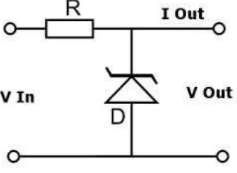
Figure 1.1 shows the simple schematic diagram of zener diode regulator
3
Next generation of computer microprocessors will operate at significantly lower voltages and higher current than today’s generation. At the same time these microprocessor, or other electronic device like LED and wireless sensor require a accurate power supply voltage regulation which can not be achieved by centralized power system. A specified regulation accuracy can be accomplished with the distributed power system where a high-quality power is delivered to the LED device by a voltage regulator module. Generally, the VRM is required to have a high power density and to operate with a high efficiency.
To meet these requirements and to provide a fast transient response, the power conversion must be performed at a high switching frequency, which presents a serious design challenge While using this bio-battery voltage regulator is more important component who is making this experiment successful. Voltage regulation is found on nearly every distribution circuit. It is important to maintain a consistent voltage so that lighting, appliances, motors, and the power system itself work as efficiently as possible.
4
However, the produced MFC is not constant enough for considered as a reliable power source, so regulation is necessary for application. The voltage regulator adjust the input voltage to a set internal reference voltage. This means that the voltage regulator is programmable by means of a network. Typically microbial fuel cell output is 0.5 volts per cell. To achieve a higher voltage, multiple cells are used in series to increase the voltage. For reliability, 3.0v is set the minimum voltage. A minimum of six cells are necessary to keep the battery, the regulating circuit and the measuring circuit.
The battery’s circuit design consist four options. Each design carefully considered the needs of the circuit and needs of the battery. The need of circuit included voltage, current and power to unable the circuit to operate correctly. Beyond this point circuit needed adjustment to make sure that the voltage level of 5.0v and current level of 100mA to 500mA according to the required of device. The circuit functionality must be verifiable and not harm to the MFC. The first design used specialized parts, such as a low input linear voltage regulator and a low input voltage bipolar junction transistor(BJT). If the current output of the MFC dipped, the resulting voltage will not effect the output voltage and circuit’s functionality. This design has an active voltage measurement that increase the energy loss in the circuit.
The second design used switching voltage regulator with a diode, resistor. This design require more power than the second design but this design is 40% more efficient. This circuit require the external reference in order to supply the desired current. It is not possible to do since, it require the external source to power up. The third design would implement a maxim simple boost controller conjunction with one inductor, one capacitor, one diode, one Mosfet, capacitors and resistor as well. But it will have an efficiency of 80-90 %.
5
using only few milli-watt range but the digital unit is more reliable than analog unit. Both the analog and digital voltmeter are needed.
1.2 OBJECTIVE PROJECT
I) To design the stabilize voltage from bio-battery
II) To obtain different stabilized Dc power which is enough to power led or equal current.
1.3 PROBLEM STATEMENT
The materials used in lithium batteries are toxic and harmful to the environment. Bio batteries are save, long term and environment friendly. To bring bio battery in commercial use, it is necessary to stabilize the output voltage to satisfy different DC requirements for light and wireless sensor nodes.
1.4 SCOPE OF PROJECT
6
CHAPTER 2
2.1 STUDY BACKGROUND
Voltage regulator is an electronic circuit used to maintain a level amount of voltage in an electrical line. It eliminates power surges which can cause harm to sensitive electronics. Lithium battery is quite expensive, toxic and flammable while bio battery is long-term and cheaper. Research of bio battery is still under process. The output from the bio battery is not stable. Sony and Nokia launch bio battery mobile models but the output can not be stabilized. In this project i am going to use DC voltage regulator to stabilize the Vout from the bio battery, that will help to finish the battery timing problems and its negative effects as well. A voltage regulator or stabilizers are used to compensate for voltage fluctuations in mains power, these are used in devices like refrigerators,
televisions and air conditioners etc. Many simple DC power supplies regulates the voltage using series or shunt regulators, but most apply a voltage reference using a shunt regulator. If the stabilizer provide more power, the shunt regulator will only provide the standard required output to the electronic device.[1]
2.2 LITERATURE VIEW SUREVEY
7
Figure: Simple Electrode Diagram
The chemical reactions in the battery cause a buildup of electrons at the anode. This results in an electrical difference between the anode and the cathode. You can think of this difference as an unstable build-up of the electrons. The electrons want to rearrange themselves to get rid of this difference. But they do this in a certain way. Electrons repel each other and try to go to a place with fewer electrons. In a battery, the only place to go is to the cathode. But, the electrolyte keeps the electrons from going straight from the anode to the cathode within the battery. When the circuit is closed (a wire connects the cathode and the anode) the electrons will be able to get to the cathode. In the picture above, the electrons go through the wire, lighting the light bulb along the way. This is one way of describing how electrical potential causes electrons to flow through the circuit [2].
2.2.1 FIRST BIO-BATTERY
8
added to the mixture, the anode garners the electrons and hydrogen ions. When the battery generates power, the protons travel to the cathode through the electrolyte to combine with the oxygen to produce water. Since the biocatalysts (enzymes) are very selective catalytically, the miniaturized bio-fuel cell could in principle be fabricated as a membrane-less fuel cell. Bielefeld iGEM team is to develop an environmentally friendly bio-battery (Microbial fuel cell -- MFC), which directly transforms bacteria into energy. Batteries such as these work in the same way as conventional batteries, but with one difference. [3].
The MFC consists of two separate units, the anode and the cathode components, just like the batteries now in current household use. A partly permeable membrane separates the two areas. In contrast to conventional batteries, however, there are bacteria in the anode area of the bio-battery instead of electrolytes. These break down substrates, in this case glucose, in a metabolic process. This produces electrons that after starting from the anode are finally delivered in an external loop to the cathode. The external circuit is then the one with the battery-powered application, for example, for lights or small motors. In this way, bacteria can produce electric energy. The bio-battery offers an array of advantages. Due to their simple construction they can be used in regions where there is shortage of electricity, for example, such as in developing countries. An advantage that the bio-battery has over other regenerative energy sources [4].
such as solar and wind power is that they are not dependent on the weather. In the case of bio-batteries, the more nourishment the bacteria receive the more energy they produce.
9
the material (refill) without any unreasonable difficulty. There must be a feed indicator for letting the user know that it is time to feed. The circuit implemented for monitoring and regulating the voltage should use minimum possible power from the MFCs. In case the circuit fails, the Biobattery should still provide a voltage output and also let user know about the failure. The Biobattery case must protects its contents from the outside world and protect the outside world from the Biobattery contents. The terminals from the Biobattery must be easily accessible for a user to power a device. The circuit must protect itself and the connected device from any voltage spikes, so it must provide a stable voltage and not cause any damage to connected device when functioning properly. The circuit must also ensure that it does not inadvertently damage the MFC itself.
Microbial fuel cells (MFC) have been in research papers since the early 1970s. Three main types have received the most attention in the last 15 years: heterotropic, photoheterotropic and sediment cells. Heterotropic and photoheterotropic cells use suspended bacterial cultures to produce current. Sediment cells are historically made with sediment found from the local body of water, using an electrode and cathode (electrically conductive metals) placed in the sediment and water above the sediment. Heterotropic cells have consistently provided higher power to surface area ratios which allow for smaller electrode areas.[6]
10
available for electron collection. The greater number of pores also helps prevent clogging. In the anode compartment, MFC transfer the electrons to the electrode. Pili, also known as nano-wires, are the appendages of MFC, the electrons produced are carried to the electrode via these pili as these cling on the surface of the electrodes. The cathode, which is also the graphite electrode, collects the electrons which flow from the anode. In the cathode compartment, oxygen acts as the final electrons acceptor.[7]
Fuel Cell Arrangement Three options exist for the fuel cell arrangement; series, parallel or both. When the fuel cells are in series, the voltages of each cell will add together. If one of the cell’s outputs becomes unusable, it will short the circuit between the rest of the cells. In the final design, this has the potential to become difficult to repair. As a result, one small malfunction can cripple the entire battery, such as the death of the bacteria in one of the cells. While this option can possibly suffer from lower voltage output, the current is additive. If one cell fails, the same voltage will result. [8]
For thepurpose of having a reliable current and voltage, the fuel cell arrangement decision needs careful consideration. Therefore, Author decided to use a combination of both parallel and series for the fuel cell arrangement. The fuel cell arrangement requires a compromise between the two of these options, which leads to the third option. By placing a small amount of resistance between the fuel cells and running half of the fuel cells in series with the other half in parallel, one can simultaneously receive the result of having a circuit in both series and parallel.[9]
11
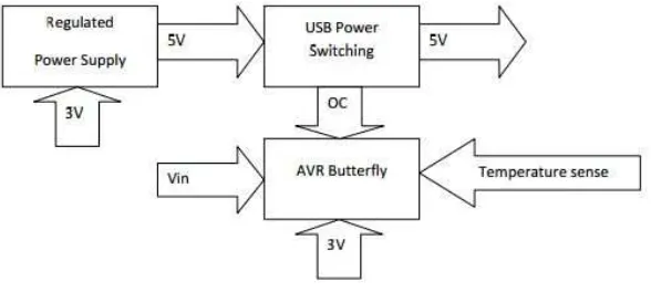
Power Management The next major module in the bio-battery design is Power Management. The voltage produced by the MFC needs regulation before powering a load is feasible. A USB female port will power a load. In order to power a USB device, a USB power switch is necessary. Along with the regulation of voltage, Power Management module will also monitor the system status. The following diagram is a basic inflow and outflow of voltages and signals.
Feeding Microbial fuel cells contain bacteria that must have a sufficient supply of “food” to survive. In fact, the power generation performance of a microbial fuel cell is dependent on food supply. Since the bacteria must live in an anaerobic environment, the method of adding the food to the cell solution requires finesse. The food supply can be added to the cell solution periodically in controlled amounts through a process called batch feeding. At feeding time, the solution must be maintained while the food supply is added and the waste solution is simultaneously removed. Unfortunately, batch feeding must be done at relatively frequent intervals, and the power output can drop significantly starting about one week after last feeding. To solve the problems associated with batch feeding, researchers have employed continuous feeding.[10]
12
On the other hand, continuous feeding systems are complicated and expensive to implement. Pumps would be necessary to continually draw the food supply into the microbial fuel cell; the power for such pumps would use more energy than the bio battery could possibly generate, rendering them unfeasible. To know and study the output the most important criterion in designing the Monitor is that the power consumption by this unit has to be at minimum. Monitor will be sharing the power generated by MFC with Regulator. The bulk of the power generated needs to go towards the load, which will connect to the bio-battery to ensure that the Monitor itself needs little power to operate. Since the biobattery is a green product, it is essential that any component used for monitoring.The most important criterion in designing the Monitor is that the power consumption by this unit has to be at minimum. Monitor will be sharing the power generated by MFC with Regulator. The bulk of the power generated needs to go towards the load, which will connect to the bio-battery to ensure that the Monitor itself needs little power to operate. [12]
13
system performing the same function. Even though it is more effective to use digital system to monitor voltage, temperature and current, it is still better to leave the monitoring of feed and waste to user. The change of feed and waste will occur over the period of days so that it does not need continuous monitoring. The use of sensors to measure feed and waste level will only complicate the system without providing any major benefit.To explain the operation of the regulator is important. An input into the voltage regulator circuit enters the circuit. Throughout the circuit are capacitors, each of which holds a charge before discharging over time. The only exceptions to this for functionality are the feed forward and feedback capacitors, which ensure proper switching and ripple at the feedback pin. If too much ripple occurs, the result will show at the output as well. [13]
Likewise, the inductor discharges over time as well, making the MOSFET act like a switch to prevent too much or too little charge from going to the output. The MAX1524 chip senses this so that the chip will boost the voltage when the voltage and current are enough to turn the chip on from its soft-start mode. If the chip senses too much voltage, a fault will occur, turning the chip and circuit off. The chip has an internal reference for voltage, maintained by the voltage switching at a frequency defined by the designer, which is achievable by setting the resistance in R1 and R2, according to the calculations provided by the datasheet from Maxim. Setting this voltage divider, the desired input and output voltages become programmable into the chip. To ensure that no large changes affect the performance of the circuit, one must put the MAX1524 in bootstrap configuration (a feedback loop to prevent problems in regulation) to prompt proper regulation. However, author’s circuit currently is not in bootstrap mode due to issues discussed later. Instead, the input goes directly to the VCC pin and the SHDN pin to bring the chip into operation quicker. Also, SET goes to ground for a lower on time at that pin, which achieves a lower range for the duty cycle to handle any given load. [14]