COMPARATIVE STUDY OF IDEAL ENGINE TEST CELL SYSTEM AT PROTON AS COMPARED TO FKM, UTEM
SYED EDDY AFIFI BIN SYED ABDULLAH
“I admit that have read this work and in my opinion this work was adequate from scope aspect and quality to award in purpose Degree of Bachelor of Mechanical Engineering
(Automotive)”
Signature :………
Supervisor’s name : Noreffendy Bin Tamaldin
COMPARATIVE STUDY OF IDEAL ENGINE TEST CELL SYSTEM AT PROTON AS COMPARED TO FKM, UTEM
SYED EDDY AFIFI BIN SYED ABDULLAH
This technical report is submitted in accordance with the requirements of the Bachelor of Mechanical Engineering (Automotive)
Faculty of Mechanical Engineering Universiti Teknikal Malaysia Melaka
DECLARATION
“I hereby, declare this thesis entitled Comparative Study of Ideal Engine Test Cell System at PROTON as compared to FKM, UTeM is the result of my own research
except as cited in the reference”
Signature : ………
iii
DEDICATION
To my beloved father,
Tuan Hj Dr. Syed Abdullah Bin Syed Sulaiman And to my beloved mother,
Puan Hajjah Nor Asmah Binti Hj. Ishak
ACKNOWLEDGEMENT
Alhamdullillah, thanks to Allah S.W.T for its guidance and opportunity that He give to me to finish up this project. It is been a challenging moment for me to do this project but with help and guidance from my supervisor, Mr. Noreffendy Tamaldin and Mr Wan Zalimi, I have done this project successfully. I am also wanted to appreciate Mr Shakir, our university technician for his kindness to help me with the research study. His help has been a great boost for my Projek Sarjana Muda (PSM) as information on FKM, UTeM engine test cell is totally important for my research.
I would like to thanks PROTON Shah Alam personnel, especially their engineer, Mr Fozi, Mr Suhaizi, Mr Farraen and Hidayah Sulaiman for given their full commitment to me during this research period. Their information on PROTON behalf is large acknowledge by me as it is beyond my limit to achieve that. I really appreciate their professionalism and friendship.
v
ABSTRACT
ABSTRAK
vii
TABLE OF CONTENTS
CHAPTER CONTENTS
DECLARATION DEDICATION
ACKNOWLEDGEMENT ABSTRACT
ABSTRAK
TABLE OF CONTENT LIST OF FIGURES LIST OF TABLES NOMENCLATURE
CHAPTER I INTRODUCTION
1.1 Problem Statement
1.2 Objective
1.3 Scope
1.4 Chapter Summary
CHAPTER II LITERATURE REVIEW
2.1 Engine Dynamometer Test Cell
2.2 Dynamometer
2.3 Engine Dynamometer Concept
2.4 Type of Dynamometer
2.5 Control Console and Data Acquisition
CHAPTER CONTENTS
2.6 Ventilation and Air Conditioning System
2.7 Engine Cooling System
2.8 Adequate Fire and Safety Precautions
System
2.9 Electrical System
2.10 Fuel Storage and Supply System
2.11 Engine Exhaust System
CHAPTER III METHODOLOGY
3.1 Introduction
3.2 Research on FKM, UTeM Engine Test
Cell
3.3 Research on PROTON Engine Test Cell
3.4 Testing Capabilities
3.5 FKM, UTeM Test Cell - Engine Testing
Requirement
3.6 PROTON Test Cell - Engine Testing
Requirement
CHAPTER IV RESULTS AND DISCUSSION
4.1 Comparative Analysis
4.2 Identify Problem
CHAPTER V CONCLUSION AND RECOMMENDATIONS
5.1 Conclusion
5.2 Recommendations
5.3 Recommended Operating Procedure
ix
CHAPTER CONTENTS
REFERENCES BIBLOGRAPHY APPENDICES
LIST OF FIGURES
NO. TITLES
2.1 An Open Thermodynamic System 2.2 Test Cell With Regenerative Electrical
Dynamometer
2.3 Output Diagram of Cell Thermal Analysis Software
2.4 Engine Test Cell
2.5 Eddy Current Dynamometer Layout 2.6 Hydraulic Dyno Schematic
2.7 Open Cooling Water System 2.8 Service Module Circuit
2.9 Typical Fuel Day Tank System 2.10 Engine Fuel Pressure Control System 2.11 Lubricating Oil Cooling Unit and
Conditioning Unit 3.1 Methodology Flowchart
3.2 Mustang Dynamometer MD-DEG 150 3.3 Manual Controller
3.4 Engine Cooling System
3.5 Dynamometer Cooling System 3.6 PROTON Engine Dynamometer
xi
NO. TITLES
3.7 Froude-Consine Eddy Current Dynamometer
3.8 TEXCEL V6 Control and Data Acquisition System
3.9 PROTON Ventilation System Illustration Design
3.10 Low Level Inlet and High Level Outlet Ducted System
3.11 PROTON Cooling System 3.12 PROTON Electrical System 3.13 PROTON Fuel System
3.14 PROTON Fire Alarm and Safety System
3.15 Sample Engine Testing Result
5.1 Heat Exchanger Diagram
5.2 Transducer Box and Signal Conditioning
LIST OF TABLES
NO. TITLES
2.1 Engine Control and Dynamometer Control Sequences
2.2 Instrumentation and Transducer Required For Measurement
2.3 Ventilation Ducts Layouts
2.4 Characteristic of Major Fire Suppression System
2.5 Electrical Power Supply Specification 2.6 Test Cell Exhaust Layout
3.1 UTeM Dynamometer Technical Data 3.2 UTeM Dynamometer Specification 3.3 Features and Characteristics of
Dynamometers
3.4 Froude-Consine Eddy Current Dynamometer Specification Data 3.5 AG 150 Froude-Consine Eddy Current
Dynamometer Technical Data
3.6 AG 250 Froude-Consine Eddy Current Dynamometer Technical Data
3.7 Standard Signal Conditioning Packages 3.8 Ventilation System Requirements
xiii
NO. TITLES
3.9 Minimum Dyno Water Pressure 3.10 PROTON Water Pressure Set Up 3.11 Electrical System Requirements 3.12 Testing Capabilities Table
3.13 Parameter Monitored at PROTON 4.1 Test Cell System Comparison 4.2 Comparative Analysis Summary 5.1 Standard Size of Transducer Box
PAGE
NOMENCLATURE
A.C = Alternate Current
AG = Air Gap
AHU = Air Handling Unit BIPO = Break In and Pass Off
CO2 = Carbon Dioxide
D.C = Direct Current
DGEC = Dry Gap Eddy Current DTC = Digital Throttle Control ECU = Electronic Control Unit
F = Force, N
FCU = Fuel Controller Unit
FKM = Fakulti Kejuruteraan Mekanikal FMS = Fuel Measurement System IGBT = Insulated Gate Bipolar Transistor
LVDT = Linear Variable Displacement Transducer MUT = Machine under Test
MD = Mustang Dynamometer
xv
P = Power, kW
PID = Proportional, Integral, Derivative PLC = Programmable Logic Controller
PROTON = Perusahaan Otomobil Nasional Sdn Bhd PRT = Platinum Resistance Thermometers
R = Distance, m
S = Shaft speed, rpm
SAE = Society of Automotive Engineering
T = Torque, Nm
TDC = Top Dead Centre
UTeM = Universiti Teknikal Malaysia Melaka VAC = Volt Alternate Current
CHAPTER I
INTRODUCTION
1.1 Problem Statement
Engine dynamometer is a dynamometer that coupled directly to an engine that has been removed from a vehicle and it been used to measures power and torque directly from the engine crankshaft or flywheel. Engine dynamometer is usually placed in the test cell which has sufficient system to support engine dynamometer when running. A standard test cell is equipped the engine dynamometer with various system such as ventilation system, cooling system, control console and data acquisition system, fire and safety precaution system, fuel system, electrical system and engine exhaust system.
2
1.2 Objectives
The goal for this project is to investigate an ideal working principle of an engine test cell and to perform comparative analysis of the existing engine test cell in FKM, UTeM and the engine test cell at PROTON facilities. The objectives of this project also include performing recommendation and provide benchmark of engine testing procedure for existing engine test cell in FKM, UTeM.
1.3 Scopes
The scopes for this project is involving running a sample of engine testing at PROTON and obtained a typical engine testing data for analysis. Identification of the weaknesses in engine test cell system in FKM also needs to be done. The scope also includes analyzing the problem with the current testing procedure in FKM, UTeM. Finally, this standard operating procedure obtained could be use as reference in running any engine testing in FKM engine test cell.
1.4 Chapter Summary
1.4.1 Chapter 1: Introduction
1.4.2 Chapter 2: Literature Review
This chapter explains about the standard engine test cell setup including explanation on the system related to the test cell and type of engine dynamometer that can be used.
1.4.3 Chapter 3: Methodology
This chapter describes the methodology used in order to achieve the project’s objective. In this project, research on the FKM, UTeM test cell and PROTON test cell is performed to understand both test cell system. This study also involves the testing capabilities of both test cells in order to run various types of testing and the engine testing requirements for both test cells. In an engine testing requirements, there are few consideration been made based on before running the engine testing such as parameter monitor, operational procedure, data logging, engine cooling and safety precaution.
1.4.4 Chapter 4: Results and Discussion
4
1.4.5 Chapter 5: Conclusion and Recommendation
CHAPTER II
LITERATURE REVIEW
2.1 Engine Dynamometer Test Cell
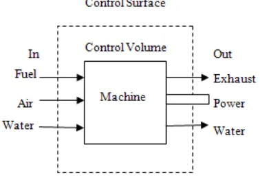
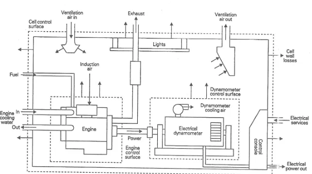
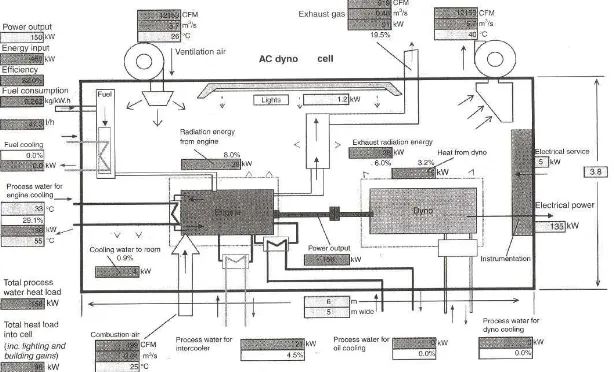
[image:22.612.234.423.521.655.2]A test cell is a room used to develop, characterize and test engines. The facility allows engine operation in different operating condition and offers measurement of several physical variables associated with the engine operation. In almost all engine test cells, an open thermodynamics system is used where it helpful in considering the total behavior of a test cell. With this concept, all the mass and energy flows into and out of the system is identified through balance sheet. Figure 2.1 shows the schematic diagram of an open thermodynamic system. Figure 2.2 shows the diagram of the standard engine test cell with regenerative electrical dynamometers. Figure 2.3 shows the output diagram of cell thermal analysis software.
6