UNIVERSITI TEKNIKAL MALAYSIA MELAKA
RCCB CONTROL FOR HOME USING GSM
This report submitted in accordance with requirement of the Universiti Teknikal Malaysia Melaka (UTeM) for the Bachelor Degree of Engineering Technology
(Electronic Industry) (Hons.)
by
AMAR FAIZ BIN ABDUL GHANI B071210316
901222-02-5827
UNIVERSITI TEKNIKAL MALAYSIA MELAKA
BORANG PENGESAHAN STATUS LAPORAN PROJEK SARJANA MUDA
TAJUK
RCCB CONTROL FOR HOME USING GSM
SESI PENGAJIAN: 2014/15 Semester 2
Saya AMAR FAIZ BIN ABDUL GHANI
mengaku membenarkan Laporan PSM ini disimpan di Perpustakaan Universiti
Teknikal Malaysia Melaka (UTeM) dengan syarat-syarat kegunaan seperti berikut:
1. Laporan PSM adalah hak milik Universiti Teknikal Malaysia Melaka dan penulis. 2. Perpustakaan Universiti Teknikal Malaysia Melaka dibenarkan membuat salinan
untuk tujuan pengajian sahaja dengan izin penulis.
3. Perpustakaan dibenarkan membuat salinan laporan PSM ini sebagai bahan pertukaran antara institusi pengajian tinggi.
4. **Sila tandakan ( )
SULIT
TERHAD
TIDAK TERHAD
(Mengandungi maklumat yang berdarjah keselamatan
atau kepentingan Malaysia sebagaimana yang termaktub
dalam AKTA RAHSIA RASMI 1972)
(Mengandungi maklumat TERHAD yang telah ditentukan
oleh organisasi/badan di mana penyelidikan dijalankan)
(TANDATANGAN PENULIS)
Alamat Tetap:
NO. 132 KAMPUNG TELOK JAMAT
06400 POKOK SENA
KEDAH DARUL AMAN
Disahkan oleh:
(TANDATANGAN PENYELIA)
Cop Rasmi:
** Jika Laporan PSM ini SULIT atau TERHAD, sila lampirkan surat daripada pihak berkuasa/organisasi
berkenaan dengan menyatakan sekali sebab dan tempoh laporan PSM ini perlu dikelaskan sebagai
iv
DECLARATION
I hereby, declared this report entitled ―RCCB CONTROL FOR HOME USING GSM ‖ is the results of my own research except as cited in references.
Signature :………
Name : ………
v
APPROVAL
This report is submitted to the Faculty of Engineering Technology of UTeM as a partial fulfillment of the requirements for the degree of Bachelor of Engineering Technology (Electronic Industry) (Hons.). The member of the supervisory is as follow:
vi
ABSTRACT
vii
DEDICATIONS
I lovingly dedicated this Final Project Report to:
viii
ACKNOWLEDGMENTS
In the name of Allah S.W.T the most gracious and merciful ,praise to Allah the lord of universe and may blessing and peace of Allah be upon his messenger Muhammad S.A.W .First ,and foremost thank for giving me wellness and idea to do this project. Without any of it, I surely cannot complete this project in the time given. Alhamdulillah and grate full to all might give me opportunity and able to complete the final year project for final year student. Before complete this report i was contact with many people researches ,academician and practinoiners. They also give good recommendation and also understanding about this project.
In particular, I wish to express my sincere appreciation to my main project supervisor, Sir Tengku Faizal Bin Tengku Wook or encouragement guidance, critics and friendship. I am also very thankful to for her guidance, advices and motivation. He always gives the idea and knowledge in helping me to carry out the PSM in a better way. His knowledge is very useful for me to do the research appropriately Without their continued support and interest, this final report would not been the same as presented here.
ix
LIST OF SYMBOLS AND ABBREVIATIONS ... Error! Bookmark not defined. ... 1
Chapter 1 1.0 Introduction of the project ... 1
x
Over Current Fault ... 11
Short circuit Fault ... 12
Lightning Fault ... 12
3.2 Hardware and Development ... 22
3.2.1 Residual Current Circuit Breaker(RCCB) ... 22
3.2.2 Isolator ... 23
3.2.3 Miniature Circuit Breaker(MCB) ... 24
3.2.4 Relay ... 26
3.2.5 GSM Modem ... 28
3.2.6 PIC 16F877A ... 29
3.2.7 MAX 232 IC ... 30
3.2.8 Voltage Regulator(LM7805) ... 31
3.2.9 Push Button ... 32
xi
3.6 Software Implementation ... 42
3.6.1 ISIS 7 Professional by Proteus ... 42
3.6.2 MicroC PRO for PIC software ... 43
3.6.3 C Language ... 44
3.6.4 AT Command ... 45
3.7 Design Method ... 46
3.8 Flow Chart Explanation ... 47
3.9 Project Overview ... 48
... 50
Chapter 4 4.0 Introduction ... 50
xii
4.1.1 TEST COMUNICATION GSM AND MOBILE PHONE ... 51
4.1.2 ACTIVE SYSTEM ... 52
4.1.3 RCCB TRIP ... 53
4.1.4 TURN ON RCCB BACKUP ... 54
4.2 Analysis and Discussion ... 55
4.2.1 Analysis the time between GSM and Output Display ... 55
4.2.2 Analysis about PIC 16F877A and 18F877A ... 56
4.2.3 Analysis about GSM ... 57
4.2.4 Analysis about (SMS receive and sending) ... 58
4.3 Problem Encounter ... 58
CHAPTER 5 ... 59
5.0 Introduction ... 59
5.1 Conclusion ... 59
5.2 Recommendation ... 60
APPENDIX A ... 62
APPENDIX B ... 64
APPENDIX C ... 73
APPENDIX D ... 75
xiii
LIST OF FIGURES
Figure 2.1 Residual Current Circuit Breaker voltage operate ... 8
Figure 2.2Residual Current Circuit Breaker (RCCB) current operate ... 9
Figure 2.3 :PIC 16F877A Pin... 15
Figure 3.1:Project Methodology ... 19
Figure 3.2:Block Diagram ... 20
Figure 3.3:Residual Current Circuit Breaker(RCCB) ... 22
Figure 3.4:Isolator ... 23
Figure 3.5:Miniature Circuit Breaker (MCB) ... 24
Figure 3.6:Relay ... 26
Figure 3.7:Relay Diagram ... 27
Figure 3.8GSM Modem ... 28
Figure 3.9:PIC 16F877A ... 29
Figure 3.10:MAX 232 ... 30
Figure 3.11:Typical MAX 232 Circuit... 30
Figure 3.12:LM 7805 ... 31
Figure 3.13Push Button ... 32
Figure 3.14:PCB Layout of soldering side ... 34
Figure 3.15PCB Layout of Component side ... 34
Figure 3.16:PCB cleaning process ... 37
Figure 3.17ISIS 7 Professional Software ... 42
Figure 3.18MicroC PRO for PIC Software ... 43
Figure 3.19:C Language ... 44
Figure 3.20Flow chart of the design process methodology ... 48
Figure 4.1:TEST COMUNICATION GSM N MOBILE PHONE ... 51
Figure 4.2mobile phone display upon activating the system ... 52
Figure 4.3:mobile phone display ―NO POWER : after earth fault, (b) From prototype bulb is condition ―OFF‖ ... 53
xiv
LIST OF TABLE
1
Chapter 1
INTRODUCTION
1.0 Introduction of the project
Many of project in the world also used applications of the Global System for Mobile communication (GSM) technology. Besides that in this project I also design Distribution Board Controller using SMS implements the emerging applications of the Global System for Mobile communication (GSM) technology .By using combination of GSM modem, PIC16F877A, and relays, it creates a control system that will act as embedded system which can monitor the situation of Residual Current Circuit Breaker (RCCB).the system also energize the backup RCCB device that placed near to the first RCCB in the distribution board if any earth faults happen to the first RCCB.this system allow users receive status of the RCCB and also can sent command via mobile phone in form of Short Message Service (SMS).The operation of this project is receiving the sent SMS and processing as required to perform the operation and give information of short circuit occur in RCCB.To continous the operation of RCCB based on users send SMS to GSM.
The Short Messages Services (SMS) in GSM allows among other the transmissions of short text messages to mobile phones. In cases of an emergency the SMS can be used to warn a large number of individual. SMS also can be used to control the some system like a control the flood warning, control the water pumps and so on. To control the system using SMS, GSM module and GSM remote control will be used.
2
anything from home devices such as alarm, heating, and so on, to commercial security system such as routers and server and the like can be remotely controlled.
In essence, a GSM remote control is one of the most useful things out there. It can be turned to any practical use. The unit sits on the mobile phone network and is assigned a regular mobile number accordingly. Calling this number or even send a text will engage the unit, thus giving control of the end device it is connected to.
The GSM remote control can be set up to only engage when received from authorized numbers (secure control) or from any number across the world (open access control). As such, any device can be controlled from anywhere.
This project monitors the distribution board to find out when the circuit breaker trips. When the trip and cut off supplies, GSM will send SMS notify main circuit breaker trip earth leakage or short circuit happen. Then the user can send SMS to activate the backup circuit breaker to continue to supply electricity to the house. Way to detect electricity is to use AC relay acts as a sensor.
1.1 Background
Nowadays in our life we know the technology grow up very fast. Technology is a broad concept that refers to use and knowledge of tools and crafts and how these tools and crafts affect our ability to control and adapt to the environment. In human society today, technology is a result of science and engineering. We all need the technology to make our activity in everyday easier. Every second the new technology will produce. Now a day every country always keep going to do research and developing the safety, in manually or technically. It is because safety is most important for all generation. On other reason, almost every country has highly criminal force the government to reduce theft of essential items.
3
fact that improvements are in fact possible and these improvements have eased our life and the way we live. Remote management of devices is a subject of growing interest and in recent years it can be seen many systems providing such controls.
These days, apart from supporting voice calls a mobile phone can be used to send text messages as well as multimedia messages (that may contain pictures, graphics, animations, etc). Sending written text messages is very popular among mobile phone users. Instant messaging, as it is also known, allows quick transmission of short messages that allow an individual to share ideas, opinions and other relevant information. The uses of concept a system that acts a platform to receive messages that is in fact are commands sent to the system and relay will allow current flow through other circuit breakers that connected to the platform. A control system that is based on the GSM technology has been design that effectively allows control from a remote area to the desired location.
The application of the system is immense in the ever-changing technological world. It allows a greater degree of freedom to an individual to monitor and controls the distribution board. The need to be physically present at the nearer area of the distribution board is eliminated with the use of this system.
1.2 Problem Statement
4
By using this project it can solve problem by energize the backup RCCB using mobile phone as a remote control and SMS as the technology .It will ensure the safety of user and reduce the wastage time to repair the distibution board by manualy and can know the cause of trip in distribution board.
1.3 Objective
The main objective of this project is to design study and develop a system protect for distribution board. The main objective of the project is to give easier to the user far from home, office, how there can be sure their home or offices are safe. With this system can help a user to secure the building from anywhere and anytime.
To backup electricity for important electrical appliance To monitoring the distribution board
To make it easier and no longer need to manual reset To maintain the distribution board is safe for user
To create a controller that is able to control of devices from one particular location
1.4 Scope of Project
5
Chapter 2
LITERATURE REVIEW
2.0 Introduction
Residual Current Circuit Breaker (RCCB) is important equipment to protection or security must have in wiring installation for each resident building.The main mechanism in operation is tripping coil which is it can be operation either in live or off condition.
An unintentional ,electrically conducting connection between an ungrounded conductor of an elctrical circuit and the normally non current carrying conductors,metalic enclosures,matallic raceways, metallic equipment or earth. Such an imbalance may indicate current leakage thought the body of person who is grounded and accidentally touching the energized part of the circuit. A lethal shock can result from these condition.RCCB are designed to disconnect quickly enough to prevent injury caused by such shock. They are not intended to provide protection against overcurrent (overload) or short circuit condition
6 Features of RCCB
Special Magnetic material and highly sensitive miniature relay is used to ensure positive detection of low Earth leakage current.
High quality thermoset insulating fire retardant Housing Reliable mechanical operation
Incorporated advanced neutral hence suitable for as a Main switch Fast acting and long life trip free mechanism
High contact life
Ease of Mounting and cabling
ELCB operate by measuring the current balance between two conductors using a differential current transformer. The device will open its contacts when it detects any difference in current between the line conductor and the neutral conductor. The supply and return currents must sum to zero, otherwise there is a leakage of current to somewhere else (to earth/ground, or to another circuit, etc.)
7 The Difference between RCCB and ELCB
• ELCB is the old name and often refers to voltage operated devices that are no longer available and it is advised you replace them if you find one.
• RCCB or RCD is the new name that specifies current operated (hence the new name to distinguish from voltage operated).
• The new RCCB is best because it will detect any earth fault. The voltage type only detects earth faults that flow back through the main earth wire so this is why they stopped being used.
• The easy way to tell an old voltage operated trip is to look for the main earth wire connected through it.
• RCCB will only have the line and neutral connections.
• ELCB is working based on Earth leakage current. But RCCB is not having sensing or connectivity of Earth, because fundamentally Phase current is equal to the neutral current in single phase. That‘s why RCCB can trip when the both currents are deferent and it withstand up to both the currents are same. Both the neutral and phase currents are different that means current is flowing through the Earth.
• Finally both are working for same, but the thing is connectivity is difference.
• RCD does not necessarily require an earth connection itself (it monitors only the live and neutral).In addition it detects current flows to earth even in equipment without an earth of its own.
8
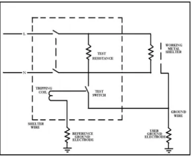
2.1 Voltage Operated
This circuit breaker voltage types is operating with increasing for metal shelter cause of current earth leakage .When earth leakage current flow,potential for metal shelter works will inrease because of impedance earth damege short coil.This potential will make the current throught tripping coil for Residual Current circuit breaker to elctrode ground .Figure 2.1 show the circuit of Residual Current Circuit Breaker Voltage Operate.
The maximum potential is used for running this residual current circuit breaker not exceeds to 40 Volt RMS. in order that hazard of shock will decrease to minimum. However, the user used RCCB voltage types not allow to use it from Jabatan Bekalan Elektrik (JBE) because of this RCCB not suitable and less detect.
Figure 2.1 Residual Current Circuit Breaker voltage operate
9
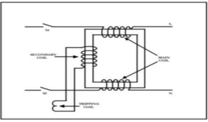
2.2 Current Operated
The circuit breaker current type is show in Figure 2.2. Refer to that figure, it has connection between earth wire and residual current circuit breaker. A transformer core is used for detect earth leakage current. In condition S1 and S2 are closed. The current which is flow in live wire is same magnitude with current back to wire neutral (N) but different direction. The field in main core will cancel with other. That will make no voltage in secondary coil.
When earth leakage happen, current damage will flow to earth coil and not flow to neutral coil. This can be difference current magnitude at main coil and disturbed stabilization magnetic for main coil. Magnetic flux will in core and voltage happen in secondary coil. This make tripping coil operate. S1 and S2 will open, and the power system will stop.
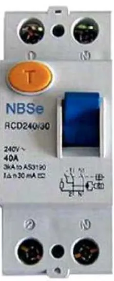
This residual current circuit breaker type is to compare current in phase conductor with current in neutral conductor. Any different current to earth may be cause of damage in system electricity. Residual current circuit breaker current type is show in Figure 2.2 and Photo 2.1 and 2.2 show type of residual current circuit breaker type used as commercial.
10
Figure 2.3: Residual Current Circuit Breaker type ABB
11
2.3 Electrical Fault
A fault is any abnormal situation in a electrical system in which the elctrical current may or not flow through the intended part.Equipment failure also attributable to some defect in the circuit ,example is loose connection,insulation failure or short circuit etc.The type fault is
1. Over current Fault 2. Short circuit fault 3. Lightning fault
Over Current Fault