DOI: 10.12928/TELKOMNIKA.v12i2.2032 297
Traveling-Wave-Based Fault Location in Electrical
Distribution Systems with Digital Simulations
Jinrui Tang*, Xianggen Yin, Zhe Zhang
State Key Laboratory of Advanced Electromagnetic Engineering and Technology (Huazhong University of Science and Technology)
Luoyu Road 1037, Wuhan 430074, Hubei Province, China *Corresponding author, e-mail: [email protected]
Abstract
Traveling-wave-based fault location in electrical distribution systems is an important safeguard for the distribution network reliability. The effectiveness of the methods is verified directly in power grid in the early stages, while different fault types can't appear in a short time. And normal dynamic physical simulation cannot meet the teaching demand either because of the limitation of transmission line model and other factors. So PSCAD/EMTDC and MATLAB are used to illustrate the the fault location methods in this paper, which can promote the traveling-wave-based fault-location technology. Meanwhile, the traveling-wave-based fault-location method based on characteristic frequencies is analyzed in this paper.
Keywords: characteristic frequency, fault location, transmission line model, traveling wave
1. Introduction
Fault location in the electrical distribution systems (EDSs) is very important for the secure and stable operation [1]. In the past decade, fault location in EDSs has been extensively investigated and several approaches have been proposed, which includes faulty feeder identification [2], fault section location [3] and fault position location [1]. With the development of smart distribution grids, fault location becomes more and more important.
The proposed fault location methods can be grouped into two categories: 1) methods based on the impedance measurement [4]-[7]; 2) methods based on the traveling waves [8]-[12].
Traveling-wave-based fault-location methods (TWFLMs) have the advantages of less influence by saturation characteristic of current transformer, fault resistance, fault type and the operating mode of system, so they have been successfully applied into transmission networks [13]. However, they can hardly be applied into EDSs because the feeders usually include many laterals.
Camparing with the wide investigation of TWFLMs, test technology of traveling-wave fault location falls behind obviously. Early verification of traveling-wave fault-location technology is difficult to operate directly in power grid, while different fault types can't appear in a short time [14]. At the same time, normal dynamic physical simulation can't meet the test demand because of the limitation of transmission line model and other factors [15]. Therefore, theoretical research and equipment development of traveling-wave fault location seriously depend on digital simulation [16].
To overcome the problems, PSCAD/EMTDC, which is widely used in electromagnetic transient simulations [16]-[17], and Matlab are used to study the TWFLMs. Meanwhile, a novel fault location method based on characteristic frequencies of the recorded transient wave is proposed.
2. Review of Traveing-wave-based Fault-location Methods
In this paper, take the fault-location methods based on characteristic frequencies as an example, PSCAD/EMTDC and MATLAB are used to show the effectiveness of the methods.
When the end of the transmission line is set as the starting point of the calculation distance x, the voltage can be represented in the time domain by [21]
0
u+ denotes the incident wave and u- represents the reflected wave. Assuming the impedance of the load equals Z2, the reflection coefficient at the end (x=0) for the voltage traveling wave is
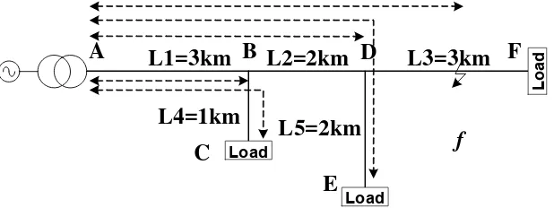
As shown in Figure 1, Ref. [10] proposed the principle of the characteristic frequencies. If the measuring point is placed at bus A and the three-phase short-circuit fault occurs at middle of line DF, the traveling wave will propagate back and forth in the paths A-B, D, C, A-B-D-E and A-B-D-f (f is the fault point). So the characteristic frequencies will exist in the recorded transient signal at bus A and can be calculated by
, propagation length of the path P and np depends on the reflection coefficients at both ends of the path. If the polarities of the reflection coefficients at both ends are the same, np equals 2. Otherwise np equals 4.
Figure 1. One typical distribution system
Once the frequencies of the recorded transient signal are identified, the fault position can be located based on equation (3).
3. Transmission Line Model in PSCAD/EMTDC
3.1. Multiple Π or T Line Model
The principle of distributed parameter circuit should be used to analyze the traveling wave propagation in transmission line. As shown in Figure 2, multiple Π or T line model is used and a short circuit fault happends at the end.
Figure 2. MultipleΠ or T line model
Assume equivalent inductance of the system is zero, from the analysis in [15], multiple
Π line model and multiple T line model have the same difference equation, the voltage at the pth chain of the line is as follows:
=1
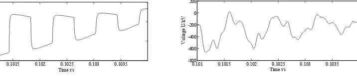
The equation (4) shows that: 1) oscillation would happend in the chain network; 2) there exists n oscillating angular frequencies which equals the number of the chains. In digital simulation or dynamic physical simulation, number of the chains can't be infinite. Then it can't simulate the traveling wave front accurately and can't meet the test demand of the fault location alogrithm based on wave-front identification as shown in Figure 3.
When n approaches to infinity, equation (5) can be derived and it is the basis of characteristic-frequency fault-location alogrithm.
Thus simulation results of multiple Π or T line model can’t describe the actual wave-front characteristics and characteristic frequency of traveling wave because of the limited number of the chains.
(a) Traveling wave in Jmarti line model[16] (b) "Traveling wave" in multiple T line model
0.101 0.1015 0.102 0.1025 0.103 0.1035
-600
0.101 0.1015 0.102 0.1025 0.103 0.1035
3.2. Bergeron Line Model
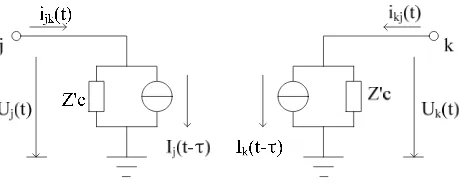
Assume parameters of the conductor are independent of frequency, Bergeron model can be used for transient calculation for lossless transmission line as shown in Figure 4. When line loss is taken into account, the total system resistance can be equivalent to lumped parameter ( 1/2 in the middle of the line and 1/4 at each end).
Actually parameters are affected by frequency due to skin effect and it is the main reason of traveling-wave dispersion. The dispersion will be more obvious in zero-mode wave. For a three-phase transmission line, comparision of the simulation results between Bergeron model and Jmarti model in which dispersion is considered is shown in Figure 5 when a single phase-to-ground fault happends.
From the analysis mentioned above, Bergeron line model can't meet the test demand of the fault location alogrithm based on wave-front identification because it ignores the traveling-wave dispersion. But traveling-traveling-wave propagation would be simulated accurately when the skin effect can be omitted. Because the frequency of the compomnent used in fault location alogri-thm based on characteristic frequency is usually low and the alogrialogri-thm doesn't need to recog-nize wave fronts [10]-[13], the dispersion has little affection on this algorithm. Thus Bergeron can be used to test the fault location algorithm based on characteristic frequency to some extent.
Figure 4. Bergeron line model
(a) Traveling wave in Jmarti line model (b) Traveling wave in Bergeron line model Figure 5. Comparision of simulation results between Jmarti and Bergeron line model
3.3. Frequency-dependent Line Model
When parameters of the conductor vary with frequency, the traveling wave propagation must be calculated in frequency domain while the electromagnetic transient calculation is easy to carry out in time domain. To solve this problem, one method is to utilize Fourier transform, another method is to treat the characteristic impedance and propagation coefficient with approximation by rational function based on Bode diagram [22] and etc.
The current on both sides of transmission line k-m is as follows:
0.099 0.0995 0.1 0.1005 0.101 0.1015 0.102 0.1025 -400
0.099 0.0995 0.1 0.1005 0.101 0.1015 0.102 0.1025
2
The line model proposed in [22] is the known Jmarti line model. In the paper two rational functions are utilized to simulate Zc(ω) and A(ω). The principle of this method is to use analog filtering technology to identify frequency-dependent parameters in fact. Based on this method, Jmarti line model is the common model used in traveling-wave fault location.
4. Analyses of the Characteristic Frequencies
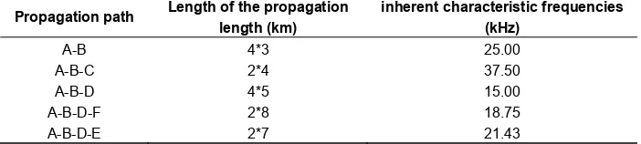
When the EDS operates normally and an impulse signal is injected at bus A, the characteristic frequencies of the recorded transient signal at bus A are called the inherent characteristic frequencies of the system.
Table 1. Inherent characteristic frequencies of the EDS showed in Figure 1
Propagation path Length of the propagation length (km)
Take the distribution system shown in Figure 1 as an example, and then the inherent characteristic frequencies can be calculated and shown in Table 1.
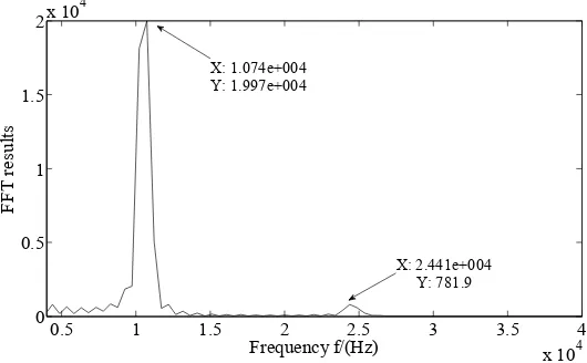
When a fault occurs in the electrical distribution system, the frequencies of the recorded signal at bus A will be diffenrent from the inherent characteristic frequencies. Take the fault at the middle of line DF shown in Figure 1 as an example, the recorded transient signal at bus A is shown in Figure 6.
Figure 6. The recorded transient signal at bus A shown in Figure 1
Figure 7. Frequencies of the recorded signal at bus A associated to the fault at middle of BC
5. A Novel Fault Location Method Based on Characteristic Frequencies
A novel fault-location method based on characteristic frequencies can be proposed. Firstly, FFT is used to extract the frequencies of the recorded signal. Secondly, the whole frequency is divied to several sub-frequency bands, and each sub-frequency band contain one of the inherent characeristics frequencies. Thirdly, the energy values of the sub-frequency bands can be calculated and normalized. Fourthly, the energy values corresponding to the typical fault positions can be obtained in advance. Finally, one a fault occurs, the following equation can used to identify the fault position.
2
1
min ( ) ,
n
if ij
j i
E E j V
(7)Where: V denotes the set of the typical fault positions in the priori database; j represents the jth typical fault position; Eif represents the energy value of the ith frequency sub-frequency band for the real fault; Eij represents the energy value of the i
th
frequency sub-frequency band for the jth typical fault position and n represents the number of the frequency sub-frequency bands corresponding to the distribution system.
0.5 1 1.5 2 2.5 3 3.5 4
x 104 0
0.5 1 1.5
2x 10 4
Frequency f/(Hz)
FFT
re
su
lts
X: 1.074e+004 Y: 1.997e+004
6. Conclusions
Digital simulations are important for the study of TWFLMs in EDSs. Using the Jmarti line model and the algorithms of digital signal processing provided in Matlab, the TWFLMs can be deeply discussed.
Because the fault-generated transient traveling wave must be transferred through transmission line, mutual inductor and secondary circuit before it is used, the modeling method of mutual inductor, including TA model, TV model and CVT model, need to be discussed in the future paper.
.
Acknowledgement
This work was supported by the National Natural Science Foundation of China (Grant No. 51177058).
References
[1] Jinrui T, Xianggen Y, Zhe Z, and et al. Iterative extraction of detected zero-mode wave velocity and its application in single phase-to-ground fault location in distribution networks. Transactions of China Electrotechnical Society. 2013; 28(4): 202-211.
[2] Roberts J, Altuve H, Hou D. Review of ground fault protection methods for grounded, ungrounded, and compensated distribution systems. Proc. 28th Annu. Western Protective Relaying Conf. 2011: 1-10.
[3] Chen WH. Fault section estimation using fuzzy matrix-based reasoning methods. IEEE Transactions on Power Delivery. 2011; 26(1): 205-213.
[4] Pradhan AK, Routray A, Gudipalli SM. Fault Direction Estimation in Radial Distribution System Using Phase Change in Sequence Current. IEEE Transactions on Power Delivery. 2007; 22(4): 2065-2071.
[5] Wan Y,Robert K. Equivalent Circuits for an SLG Fault Distance Evaluation by Curve Fitting in Compensated Distribution Systems. IEEE Transactions on Power Delivery. 2008; 23(2): 601-608.
[6] Salim RH, Resener M, Filomena AD, and et al. Extended Fault-Location Formulation for Power Distribution Systems. IEEE Transactions on Power Delivery. 2009; 24(2): 508-516.
[7] Mamdouh AA, Khalid MN. Fault Analysis of Multiphase Distribution Systems Using Symmetrical Components. IEEE Transactions on Power Delivery. 2010; 25(4): 2931-2939.
[8] Yan F, Yang Q, Qi Z, and et al. Study on Fault Location Scheme for Distribution Network Based on Travelling Wave Theory. Proceedings of the CSEE. 2004; 24(9): 37-43.
[9] Yu S, Bao H, Yang Y. Practicalization of Fault Location in Distribution Lines. Proceedings of the CSEE. 2008; 28(28): 86-90.
[10] Borghetti A, Corsi S, Nucci CA, and et al. On the Use of Continuous-Wavelet transform for fault location in distribution power systems. International Journal of Electrical Power & Energy Systems.
2006; 28(9): 608-617.
[11] Borghetti A, Bosetti M, Silvestro MD, and et al. Continuous-Wavelet Transform for Fault Location in Distribution Power Networks:Definition of Mother Wavelets Inferred From Fault Originated Transients. IEEE Transactions on Power Systems. 2008; 23(2): 380-388.
[12] Borghetti A, Bosetti M, Nucci CA, and et al. Integrated Use of Time-Frequency Wavelet Decompositions for Fault Location in Distribution Networks: Theory and Experimental Validation.
IEEE Transactions on Power Delivery. 2010; 25(4): 3139-3146.
[13] Hanif L, C. Yaman E. A machine learning and wavelet-based fault location method for hybrid transmission lines. IEEE Transactions on Smart Grid. 2014; 5(1): 51-59.
[14] Zhen W, Chen W, Chen P, and et al. Simulation method and test technology of transmission line traveling wave. Electric Power Automation Equipment. 2011; 31(6): 74-79.
[15] Tang Y, Chen H, Dai F, and et al. Selection of Transmission Line Models for Travelling-Wave Protection Studies. Proceedings of the CSEE. 1997; 17(4): 270-273.
[16] PSCAD v4.2, Manitoba HVDC Research Centre, 2006.
[17] Tang J, Yin X, Zhang Z. Modeling technology in Traveling-wave fault location. TELKOMNIKA Indonesian Journal of Electrical Engineering. 2013; 11(6): 3333-3340.
[18] Redy M, Haifa AM, Charles QS. Ground fault location on a transmission line using high-frequency transient voltages. IEEE Transactions on Power Delivery. 2011; 26(2): 1298-1299.
[20] Mert K, Hanoch LA, Ali A. Traveling-wave-based fault-location technique for transmission grids via wide-area synchronized voltage measurements. IEEE Transactions on Power Systems. 2012; 27(2): 1003-1011.
[21] Christophe C, Tatsuo I. Electromagnetic metamaterials: transmission line theory and microwave applications. Hoboken, New Jersey: John Wiley & Sons. Inc. 2005: 59-131.