DESIGN OF AUTOMOTIVE PARTS FOR
5 AXIS MILLING MACHINE
KUAH CHUEN TSE
UNIVERSITI TEKNIKAL MALAYSIA MELAKA
Design of Automotive Parts For
5 Axis Milling Machine
Thesis submitted in accordance with the partial requirements of the
Universiti Teknikal Malaysia Melaka for the
Bachelor of Manufacturing Engineering (Manufacturing Process)
By
Kuah Chuen Tse
Faculty of Manufacturing Engineering
UNIVERSITI TEKNIKAL MALAYSIA MELAKA
BORANG PENGESAHAN STATUS TESIS*
JUDUL: _______________________________________________________________ _______________________________________________________________ _______________________________________________________________ SESI PENGAJIAN : _______________________
Saya _____________________________________________________________________
mengaku membenarkan t esis (PSM/ Sarj ana/ Dokt or Falsaf ah) ini disimpan di Perpust akaan Universit i Teknikal Malaysia Melaka (UTeM) dengan syarat -syarat kegunaan sepert i berikut :
1. Tesis adal ah hak milik Universit i Teknikal Malaysia Mel aka .
2. Perpust akaan Universit i Teknikal Malaysia Melaka dibenarkan membuat sal inan unt uk t uj uan pengaj ian sahaj a.
3. Perpust akaan dibenarkan membuat salinan t esis ini sebagai bahan pert ukaran ant ara inst it usi pengaj ian t inggi.
(Mengandungi makl umat yang berdarj ah keselamat an at au kepent ingan Malaysia yang t ermakt ub di dalam AKTA RAHSIA RASMI 1972)
(Mengandungi maklumat TERHAD yang t elah dit ent ukan oleh organisasi/ badan di mana penyelidikan dij alankan)
(TANDATANGAN PENULIS)
DECLARATION
I hereby, declared this thesis entitled “Design of Automotive Parts For 5 Axis Milling Machine” is the results of my own research
except as cited in references.
Signature : ……….
Author’s Name : ………
Date : ………
ABSTRACT
Turbocharger is one of the approaches that utilize the exhaust gas of an automobile
to drive the compression device. The purpose of turbocharging is to increase the
intake pressure and the amount of air into the combustion chamber to improve the
efficiency of the engine. One of the main problems with turbochargers is that they do
not provide an immediate power boost when the accelerator pad is pressed, and the
car would accelerate forward suddenly when the turbocharger gets moving. This
study investigated how the design of a turbocharger’s turbine-compressor assembly
affects the efficiency of a turbocharger and improved the design of the
turbine-compressor assembly in term of transient response. Computational Fluid Dynamics
(CFD) program is used to simulate fluid flow of the design. And rapid prototype
machine is used to make a prototype of the turbine-compressor assembly. The major
contribution of this project is the design concept that can be implemented to other
turbocharger to reduce the effect of turbo-lag and improve the transient response of a
turbocharger.
ABSTRAK
Turbocharger merupakan sejenis kaedah menggunakan gas ekzos dalam sesebuah
kenderaan untuk menjalankan unit pemampat. Tujuan menggunakan turbocharger
adalah untuk meningkatkan tekanan udara dan kuantiti udara yang memasuki ke
dalam enjin supaya meningkatkan kecekapan enjin. Satu masalah yang terdapat pada
turbocharger ialah ia tidak membekalkan boost dengan serta-merta dan kenderaan
akan memecut secara tiba-tiba apabila turbocharger mula bergerak. Projek ini
menyelidikkan kesan rekabentuk turbine dan compressor sesebuah turbocharger
terhadap kecekapannya. Rekabentuk turbine dan compressor baru akan dicadangkan
untuk menggurangkan kesan turbo-lag. Atur cara komputer dinamik bendalir (CFD)
digunakan untuk mengkaji pengaliran gas dalam turbocharger tersebut. Prototaip
Pesat (RP) mesin digunakan untuk membuat satu prototaip rekabentuk ini.
Sumbangan utama projek ini adalah konsep rekabentuk yang boleh digunakan untuk
turbocharger yang lain untuk mengurangkan kesan turbo-lag dan meningkatkan
kecekapan sesebuah turbocharger.
DEDICATION
ACKNOWLEDGEMENTS
This research was performed under the supervision of Mr. Taufik, whom I
would like to thank for the freedom granted in carrying out this project. I also would
like to express my deep appreciation for Mr. Taufik understanding regarding the
difficulties I had during the project.
I would like to gratefully acknowledge Mr. Shahrul for his consultation on
the CNC machining. I would like to express my appreciation to Mr. Halim and Prof.
Md. Dan for being my panels and that they spend time to evaluate my report.
A special thank to my friend, Mr. Jia Chang, for his help on the ANSYS
simulation. And to all my friends who we have worked together for our projects, I
could not achieve it without their support and encouragement.
Most of all, I would like to thank my parents, for their patience and support
TABLE OF CONTENTS
LIST OF ABBREVIATIONS AND SPECIALIZED NOMENCLATURE ... xi
LIST OF APPENDICES... xii
CHAPTER 1 INTRODUCTION ...1
1.1 Background of Study ... 1
CHAPTER 2 LITERATURE REVIEW ...6
2.1 Introduction... 6
2.2 Turbocharger and Turbocharging Techniques... 6
2.3 Turbocharger Lag ... 10
2.4 Proposed Solutions to Reduce Turbocharger Lag ... 12
2.4.1 Hydraulic Assist System... 14
2.4.2 Air-injection system... 14
2.4.3 Hybrid turbocharging... 15
2.4.4 Variable Geometry Turbines (VGT)... 17
2.4.5 Sequential Turbocharging... 19
2.4.6 Power Assist Systems ... 21
2.5 Dynamics of Turbocharger ... 29
2.6 5 Axis CNC Milling Machine... 29
2.7 CAD/CAM... 30
2.8 ANSYS CFX... 31
CHAPTER 3 MATERIALS AND METHODOLOGY...33
3.1 Introduction... 33
3.2 Methodology... 34
3.2.1 Phase 1: Conceptual and Planning... 35
3.2.2 Phase 2: Design and Analysis ... 35
3.2.3 Phase 3: Machining... 36
3.2.4 Phase 4: Discussion and Conclusion ... 36
3.3 Material, Hardware and Software Requirement ... 36
3.4 Work Planning ... 37
3.5 Method to Conduct an ANSYS simulation... 39
3.5.1 Step 1 – Pre-Processor: Geometry Creation ... 39
3.5.2 Step 2 – Pre-Processor: CFX Meshing ... 39
3.5.3 Step 3 – Pre-Processor: Physics Preprocessor ... 40
3.5.4 Step 4 – Simulation in ANSYS Solver ... 41
3.5.5 Step 5 – Post-Processing: Viewing the Results ... 41
CHAPTER 4 RESULTS ...42
4.1 Introduction... 42
4.2 Technical Drawings ... 42
4.2.1 Design 1 ... 43
4.2.2 Design 2 ... 47
4.3 Mass and Inertia Reports of Design ... 51
4.3.1 Design 1 ... 51
4.3.2 Design 2 ... 52
4.4 Simulation Results ... 53
CHAPTER 5 DISCUSSION...58
5.1 Discussion on the Design... 58
5.1.1 Reduction in Volume and Masses ... 59
5.2 Design Selection ... 60
5.3 Material Selection ... 61
5.4 Discussion on the Simulation ... 62
5.4.1 The Simulation and Its Limitation ... 62
5.4.2 Air Flow Path and Changes in Temperature... 63
5.4.3 Pressure Boost Obtained ... 64
CHAPTER 6 CONCLUSION...65
REFERENCES ...66
LIST OF TABLES
Table 2-1: Summary of the Comparison Results for the First Gear Acceleration 24
Table 2-2: Summary of the Comparison Results for the Third Gear Acceleration 24
Table 3-1: Hardware and Software Requirement 36
Table 3-2: Work Breakdown Structure of Project 37
Table 4-1: Summary of Simulation 57
Table 5-1: Comparison between Design 1 and 2 60
LIST OF FIGURES
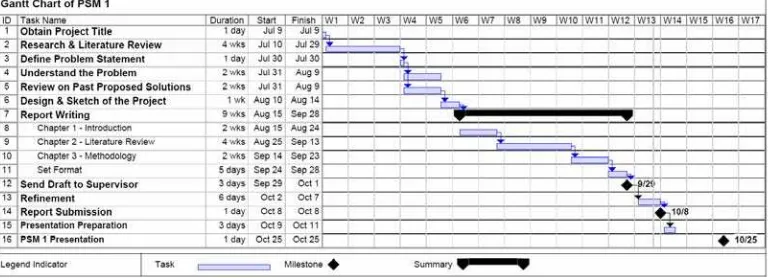
Figure 1-1: Gantt Chart of PSM 1 5
Figure 1-2: Gantt Chart of PSM 2 5
Figure 2-1: Inlet and Exhaust Gas Flow Through a Turbocharger 7
Figure 2-2: The Effect of Turbine and Compressor Wheel Size on Acceleration
Response Time to Reach Designed Maximum Boost Pressure 11
Figure 2-3: A Schematic of a Hyperbrid Supercharging System 16
Figure 2-4: VGT Turbocharger 17
Figure 2-5: Engine Speed, Vehicle Speed, Inlet Manifold Pressure and Fuel Injected
Histories during Full Power Acceleration From 0 to 60 mph. Results
Obtained by Comparing the Conventional and the VGT Turbocharger 18
Figure 2-6: BMW 535D Turbocharger System Concept 20
Figure 2-7: Twin Turbo Parallel Configuration 20
Figure 2-8: Diesel Engine with an Electric Motor in a Parallel Hybrid Configuration,
where Pem Denotes the Supplemental Power 22
Figure 2-9: Diesel Engine with a Turbocharger Power Assist System, where Pem
Denotes the Supplemental Power 23
Figure 2-10: Comparison of Torque Characteristics and Acceleration Response With
and Without TPAS 23
Figure 2-11: Comparison of Compressor Acceleration Speeds for Different Levels of
Assist Power 25
Figure 2-12: Types of Mechanical Supercharger: (a) Rotating Lobe (b) Sliding Vane
(c) Rotating Impeller (d) Orbiting Spiral 27
Figure 2-13: CFD Design Iteration 32
Figure 3-1: Flow Chart of the Project 34
Figure 3-2: ANSYS CFX Flow chart 39
Figure 4-1: Compressor Design 1 43
Figure 4-2: Compressor Design 1 44
Figure 4-3: Turbine and Shaft Design 1 45
Figure 4-5: Compressor Design 2 47
Figure 4-6: Compressor Design 2 48
Figure 4-7: Turbine and shaft Design 2 49
Figure 4-8: Turbine-Compressor Assembly Design 2 50
Figure 4-9: (A) Geometry imported into ANSYS Modeler; 53
Figure 4-10: Flow path streamline 1 54
Figure 4-11: Detailed temperature streamline profile at compressor side. 55
Figure 4-12: Simulation Summary 57
Figure 5-1: Bottom of compressor 58
Figure 5-2 Temperature change at the compressor side. (A) Top view; (B) 3D view;
LIST OF ABBREVIATIONS AND SPECIALIZED
NOMENCLATURE
CAD - Computer-aided Design
CAD/CAM - Computer-aided Design and Computer-aided Manufacturing
CAE - Computer-aided Engineering
CAM - Computer-aided Manufacturing
CATIA - Computer Aided Three Dimensional Interactive Application
CFD - Computational Fluid Dynamics
CFX - Advanced Computational Fluid Dynamics
CNC - Computer Numerical Control
ECU - Engine Control Unit
FEA - Finite Element Analysis
MRR - Material Removal Rate
NA - Naturally Aspirated
PLM - Product Lifecycle Management
TPAS - Turbocharger Power Assist System
VGT - Variable Geometry Turbine
LIST OF APPENDICES
Figure A: Housing Model 69
CHAPTER 1
INTRODUCTION
1.1
Background of Study
Automobile has become the most common and most important mean of
personal transportation. Millions of people around the world depend on their vehicle
to travel here and there. The origin of the automobile can be traced to Europe. It was
not common for people to own a car by then due to cars was so expensive. After a
century of the automobile, today, more and more people own cars.
Engine is sometimes described as the heart of an automobile. Engine is where
the burning of a mixture of fuel and air takes place and it produces mechanical
energy to drive the automobile. However, engine cannot work by itself; it has to
work together with other automotive parts, for instant, the manifold system. While
new engines are not redesigned very frequent, it has the necessity to undertake major
redesign of the manifold systems on a more regular basis, as mentioned by
Winterbone and Pearson (1999) in their studies.
Winterbone and Pearson (1999) explained how the intake and exhaust
manifolds affect engine performance, as well as emissions of noise and pollutants.
The potential for energy release in the combustion process, which is manifested as
the indicated mean effective pressure or the torque generated, is related to the
amount of air entering the cylinders. The majority of engines used in automobile
applications is naturally aspirated and operate on the four-stroke cycle, in which
distinct strokes of the piston are used to induce the air and exhaust it. There are also
supercharging, which uses a prime mover to drive the compression device; and
turbocharging, a method which utilize the exhaust gas to drive the compression
device. These methods are having the same objective that is to increase the intake
pressure and the amount of air into the combustion chamber; thus improving the
efficiency of the engine. Generally speaking, a turbocharger is more efficient than a
centrifugal supercharger. The scope of this study will be limited on the turbocharging
method only.
This study will investigate how the design of a turbocharger’s
turbine-compressor assembly affects the efficiency of a turbocharger and will try to improve
the design of the turbine-compressor assembly. Furthermore, finite element analysis
will be done on the redesigned models of the assembly to validate the designs. This
study also included machining the prototype of turbine and compressor. 5-axis CNC
machining will be used for the machining of the parts.
1.2
Problem Statement
One of the main problems with turbochargers is that they do not provide an
immediate power boost when the accelerator pad is pressed, and the car accelerate
forward suddenly when the turbo gets moving. Usually a delay is produced between
pressing on the accelerator pedal and the boost. This is due to the loss of energy to
overcome the rotational inertia of the turbine rotor. This problem is usually described
1.3
Objective of PSM
The aims of this project are to:
(a) Study and improve the design of a turbocharger turbine-compressor
assembly.
(b) Fabricate a prototype of the design using 5 axis CNC machine.
1.4
Scope of Work
The automotive part chosen for this project is the turbine-compressor
assembly inside a turbocharger. The purpose of this project is to study and improve
the design of the turbine-compressor assembly. The main focus is on the turbo-lag.
The cause of Turbo-lag will be studied and improved in the project.
In addition, a prototype of the model will be fabricated by using 5-axis CNC
machining. Before the real machining takes place, machining simulation will be
performed using CATIA; and the NC code will be generated. The parameters, for
instance, feed, speed, and material removal rate (MRR) involved in the machining
will be recorded as well.
1.5
Schematic of Project
Chapter 1 describes about the background of the study, project problem
statement, and the objective and scope of the study.
Chapter 2 highlighted some literature reviews related to the study, which
includes descriptions on turbocharger, turbo-lag, proposed technical solutions for
turbo-lag, CNC machining, CAD/CAM, and ANSYS CFX.
Chapter 3 shows the methodology and the flow of this project in detail from
the beginning.
Chapter 4 includes the result of the analysis and the presentation of data.
Chapter 5 provides a general discussion on the design, the results of the study,
stressing the significance and implications of the findings of the study.
Chapter 6 makes a conclusion on the study. Suggestions for future study are
1.6
Gantt Chart
Gantt chart has been built to give a visual presentation of the schedule of the
project flow. It shows the general sequence of project activities. Gantt chart is as well
a very useful tool to assist in tracking and monitoring the project progress. Figure 1-1
and Figure 1-2 below are the Gantt charts of the PSM 1 and PSM 2.
Figure 1-1: Gantt Chart of PSM 1
CHAPTER 2
LITERATURE REVIEW
2.1
Introduction
This section highlights some literature reviews related to the study. Firstly, an
overview of turbocharger, its significance, and its applications are presented.
Secondly, turbo-lag and its proposed technical solutions are being highlighted.
Finally, reviews of CAD/CAM and ANSYS CFX are presented.
2.2
Turbocharger and Turbocharging Techniques
Turbochargers are a type of forced induction system that compresses the air
flowing into the engine. Compressing the air introduces more air into the engine, and
more air means that more fuel can be added. Thus, more power can be provided by
the combustion process and in other word, the efficiency or power-to-weight ratio for
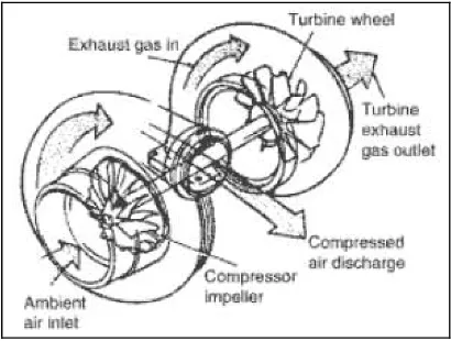
the engine is improved. The flow of gas through a turbocharger is shown in Figure
2.1.
The turbocharger itself is rather a simple device; the typical turbocharger
consisting a single turbine attached by a shaft to a single compressor. The operation
of a turbocharger is explained in detail by Aaron Joseph King (2002) in his research.
The turbine is driven by the exhaust gas at high temperature and pressure from the
exhaust manifold. The work of the turbine drives the compressor, and the air entering
quite complex. Despite the complications of transient operation of an engine, the
advantages associated with the implementation of a turbocharger are universally
accepted when applied to high efficiency diesel engines. Significant effort has been
aimed at improving the efficiency and power to weight advantages of turbocharged
engines.
Figure 2-1: Inlet and Exhaust Gas Flow Through a Turbocharger
Source: Nunney (2006)
Early turbocharging systems isolate the turbine from the inherently unsteady
exhaust flow by connecting a large exhaust plenum between the exhaust valves and
turbine. The plenum served to dampen the transient exhaust pulsations, allowing the
turbocharger to operate in an essentially steady pressure environment. This technique
is called constant pressure turbocharging. Due to the isenthalpic expansion process,
constant pressure turbocharging decreases available energy to the turbocharger. It
also results in a system of high volumetric capacitance, which degrades the system
response time to engine accelerations and decelerations.
Therefore, in an effort to utilize more of the energy available from the
exhaust flow, a technique known as pulse turbocharging has been developed and
become the dominant technology. Pulse turbocharging minimizes the expansion
losses by attaching the turbocharger to a small exhaust manifold, subjecting the
less than that which occurs in the larger manifolds of a constant-pressure system, but,
as a trade-off, the efficiency of the turbocharger subjected to pulsating flow is
typically lower. A detailed description of pulse turbocharging has been given by
Heywood (1998).
Turbochargers increase the efficiency and performance of diesel engines by
extracting more power out of a given engine. Recycling energy from exhaust gases,
turbochargers use that gas to turn a turbine, which in turn spins an air pump, which
subsequently forces compressed air into the engine’s cylinders. Without a
turbocharger, a diesel engine does not accelerate as fast as a gasoline engine.
However, a turbocharged diesel overcomes this by forcing more air into the engine.
Honeywell estimates the “turbo effect” of adding a turbocharger to a regular
diesel engine to be 70% additional fuel economy. According to a marketing research
of Gabelli & Company, Inc. in 2004, the global turbocharger market is
approximately 15 million units. Turbochargers are sold, on average, for about $200
each. According to the researcher of the report, David (2004), Turbochargers in the
personal vehicle market represent a significant opportunity for the turbocharger or
turbocharged engine manufacturers and companies.
Thus, due to the market opportunities of turbochargers, continuous efforts
have been made to improve efficiency and matching of rotary machines with internal
combustion engine over the widest possible range of operating conditions.
Ceausu (2006) mentioned that the typical boost provided by a turbocharger is
6 to 8 psi. Since normal atmospheric pressure is 14.7 psi at sea level, turbocharger is
getting about 50 percent more air into the engine. Therefore, 50 percent more power
is expected to obtained. However, nothing is perfectly efficient, so a 30- to
40-percent improvement might be obtained instead.
The turbocharged direct injected diesel engine has become an attractive