PLC CONTROLLED PALLETIZER SYSTEM
MUHAMAD ADI BIN SULAIMAN 4 BEKM
“I hereby declared that I have read through this reprt entitle PLC Controlled Palletizer System and found that it has the partial fulfillment for awarding the degree of Bachelor of Electrical Engineering (Mechatronic)
Signature :……….. Supervisor’s name : Prof Madya Mohd Ariff b. Mat Hanafiah
ii
PLC CONTROLLED PALLETIZER SYSTEM
MUHAMAD ADI BIN SULAIMAN
This Report Is Submitted In Partial Of Requirements For Degree Of Bachelor Electrical Engineering (Mechatronic)
Faculty of Electrical Engineering
UNIVERSITI TEKNIKAL MALAYSIA MELAKA
iii
“It is hereby declared that all the materials in this thesis are the results of my own work and all the materials which are not the results of my own work have been clearly acknowledge in this report”
Signature :……….. Student’s name : Muhamad Adi b. Sulaiman
iv
ACKNOWLEDGEMENT
With the name of Allah the most Beneficent and Merciful. A deep sense of thankfulness to Allah who has given me the strength, ability and patience to complete this project and thesis as it is today.
Firstly, I would like to take this opportunity to put into words my deepest gratitude and appreciation to the project supervisor, Prof Madya Mohd Ariff bin Mat Hanafiah for her support, guidance, patience, encouragement and abundance of ideas during the completion of this project. Secondly, special thanks to both honourable panels, Mohd Khairi bin Arifin for their comments, invaluable suggestions and outstanding deliberations to improve the project during the project presentation.
I would also like to express my extraordinary appreciation to my family for their invaluable support along the duration of my studies until the completion of this project. Finally yet importantly, thanks to all the persons who are directly or indirectly contributed because their perspective and guidance helped greatly to point me in the right direction until the completion of this project.
“IT IS BETTER IF YOU ARE APPROXIMATELY RIGHT THAN YOU ARE BEING PRECISELY WRONG”.
Muhamad Adi Bin Sulaiman
Faculty of Electrical Engineering
v
ABSTRACT
vi
2.2.2 Industrial Robot 7
2.2.2.1 Types of Robot 7
2.2.2.2 Technical description 8
2.3 Components of robots 12
vii
3.0 PROJECT BACKGROUND
3.0 Introduction 18
4.2 Mechanical implementation (hardware) 25 4.3 Electrical implementation (hardware) 28 4.4 Combination of mechanical and electrical parts 30
4.5 Implementation of software 31
4.6 Hardware of the system
4.6.1 Servomotor 33
4.6.2 How does it works 34
4.6.3 Servomotor Wiring 34
4.6.4 Types of Servomotor Used 35 4.6.5 Angle Calculation of Servomotor 36 4.7 Programmable Logic Controller Overview 38
5.0 RESULT
5.0 Result 39
5.1 Program of the Robotic Arm Palletizing System 41
viii
6.0 DISCUSSION AND CONCLUSION 6.0 Discussion
6.0.1 Problems encountered 43
6.1 Recommendations 45
6.2 Conclusion 45
REFERENCES 46
ix
LIST OF TABLE
TABLE TITLE PAGE
4.1 Specifications of Cytron C36S servo motor 35 4.2 Specifications of Cytron C40S servo motor 35
x
LIST OF FIGURES
FIGURE TITLE PAGE
1.1 A genealogy of project scope 4
2.1 A robot leg 13
2.2 Industrial servomotor 17
3.1 Illustration of concept for the project 19 3.2 Process Algorithms for the System 21 4.1 Overall flowchart of methodology 23 4.2 Flowchart of project implementation 24 4.3 Flowchart of literature review 25 4.4 Flowchart for mechanical implementation 27 4.5 Flowchart of electrical part 29 4.6 Flowchart for combination of mechanical and electric parts 30 4.7 Combination of hardware and software 32
4.8 Illustration of servomotor 33
4.9 Servomotor diagram 34
xi
4.11 Dimension of Cytron C36S servo motor 35 4.12 Servomotor kit from Cytron 36
4.13 DC servo motor 36
5.1 Complete palletizer robot 40
5.2 Arm robot body 40
5.3 Connection of relay and connector to PLC 40
CHAPTER 1
INTRODUCTION
1.0 Introduction
Functionally, a robot is a physical agent which is capable of executing motion for the achievement of tasks. A robot’s degree of autonomy depends on its ability to perform the order sequence of perception making and action. A robot is programmable, multifunctional manipulator designed to move material, parts or specialized devices through variable programmed motions for the performances of a variety of tasks.
Today, the robot is gaining more popularity in industrial sector such as in the
manufacturing industry. Tasks or process which can typically be accomplished by using robots include:
• Welding:
This is process of joining two of work-pieces together by applying molten weld metal.
• Cutting:
This is the process of applying thermal or mechanical energy to cut a work-piece into a specific shape. Position and velocity is important in this process
• Assembly:
This is process of either adding component to form a single entity, or affixing
2
• Material handling
This is the process of either packaging parts into a compartment (box) or
loading/unloading parts to/from another station, Position is an important parameter in this process.
The robot arm prototype that will construct in order to perform palletizing system is certain as a material handling robot.
1.1 Problem Statements
In most real industries, robots are machine that can be used to help human doing their job. Base on many factors, it is necessary for a robot to be able to reduce human job that was manually and repeatedly done such as in the manufacturing industries. Especially to handle complicated and dexterous tasks skillfully in automated manufacturing area, we often need robotic system which is capable of controlling the process.
In the industrial sector, robot arm can be used to pick some object and place it at the order side in the range of their axes. For example the robot arm is widely used in factory to pick the object from one line to other line system to continue the process. By using this robotic method, company can reduce cost to pay the labors salary. So, one approach to satisfy the industrial demands is to identically designed, fabricated and develop a robotic arm prototype.
The uses of robot in the manufacturing industry will certain have positive impact, as well:
i. Productivity:
It is impossible to achieve a high production yield using human labor because the biological system cannot deliver continuous physically effort without rest. There is no doubt that automation with robots will increase productivity.
ii. Quality of Products:
3
And, without accurate visual guidance, we cannot perform motions with any reasonable degree of accuracy or replication. Robots can not only execute accurate motions repeatedly, but are immune to the emotion states which affect human performance.
iii. Quality of Humans Life
The use of robots can free human doing dirty, dangerous and difficult job.
1.2 Project Objective
Automation systems are found in all major local factories and the industrial robot is part of many of these systems. The technicians, engineers and managers working in automated plants must have an understanding of automation concepts including basic robotic principle.
The construction, programming and operation of palletizing system is identical to most industrial robots, so a complete understanding of this system will prepare student to work on the industrial robots and automation system that used in modern factories. Besides, the objectives of this project are:
i. To study and learn the robotic arm prototype construction and its designed
ii. To designed and develop a fully automated system that is used to apply palletizing system using robotic arm prototypes.
iii. To investigate and design the command program that can be used as a controller for robotic arm system.
4
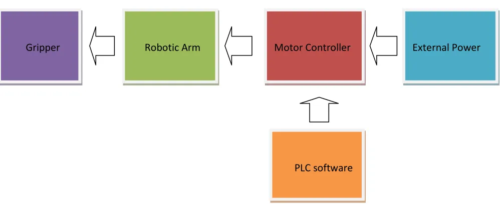
1.3 Project Scope
The basic palletizing system using controller robotic arm includes the following elements; a mechanical arm, PLC programmer, end-of-arm tooling (gripper) and external power source.
F
Figure 1.1: A genealogy of project scope
As a result of this project, the robotic arm prototype will be produced and can be controlled by using PLC programmer in order to perform the PLC palletizing system.
Gripper Robotic Arm Motor Controller External Power
5
CHAPTER 2
LITERATURE REVIEW
2.1 Previous Research
2.1.1 Graphical User Interface Development for PC-Based Control of SCARA Robotic Arm
This project has been done by Darryl Wai from Canterbury University, Christchurch, New Zealand for Final Year Project. The task undertaken in this work is a development of computer interface of a Selective Compliance Robotic Arm (SCARA). The hardware used was manufactured by Feedback Instruments and the interface had been developed for the robot.
6
Microsoft programming package, Visual Basic 6.0 was employed to develop a new interface. However, analysis from this project, the student focused only on the interfacing structure other areas such as controlling the servo. The purposed of the actuators does not addressed in the report.
2.1.2 PC-based 4 axes robot arm system.
This project has been done by Muhammad Faizal bin Zainal Abidin from Universit Teknikal Malaysia Melaka (UTeM). The student proposed an arm robot with 4 degree of freedom (DOF), computer interface by using Visual Basic 6.0. The microcontroller is used to execute the program and the motion of the robot is under supervision of computer program.
This project alike the previous project unless of microcontroller usage. This project show the inter relationship between the arm robot and personal computer. It is the good revolution of robotic system that can use PC-Based system to control the robot arm. The robot arm system can control by GUI (Graphical User Interface) to make the communication from the computer to robot arm easier. By using this PC-Based system, the robot arm system can move and the pulse of the servo motor can be set to any suitable degree to locate the arm robot to a desired position. Robot arm is a robot which able to do any job as human arms and make our lives easier, safe and more enjoyable.
2.1.3 Development of Servo Motor Pick and Place Robot.
This project has been done by Mohd Helmi Bin Suid from Universiti Teknikal Malaysia Melaka (UTeM). The student proposed an arm robot with 4 degree of freedom (DOF) as a tool for pick and place. As the actuators, he used 4 servo motors including for gripper. This robot controlled by human directly by using console (not interface with
7
control by using microcontroller which acts as the brain of the robot. The selection of PIC 16F877A made this source as the main reference for me in order for code assembly
2.2 Theoretical Background
2.2.1 Arm Robot
A robotic arm is a robot manipulator, usually programmable, with similar functions to a human arm. The links of such a manipulator are connected by joints allowing either rotational motion (such as in an articulated robot) or translational (linear) displacement. The links of the manipulator can be considered to form a kinematic chain. The business end of the kinematic chain of the manipulator is called the end-effectors and it is analogous to the human hand. The end-effectors can be designed to perform any desired task such as welding, gripping, spinning etc., depending on the application. For example robot arms in automotive assembly lines perform a variety of tasks such as welding and parts rotation and placement during assembly.
The robot arms can be autonomous or controlled manually and can be used to perform a variety of tasks with great accuracy. The robotic arm can be fixed or mobile and can be designed for industrial or home applications.
2.2.2 Industrial Robot
2.2.2.1 Types of Robot
8
Some robots are programmed to faithfully carry out specific actions over and over again (repetitive actions) without variation and with a high degree of accuracy. These actions are determined by programmed routines that specify the direction, acceleration, velocity, deceleration, and distance of a series of coordinated motions.
Other robots are much more flexible as to the orientation of the object on which they are operating or even the task that has to be performed on the object itself, which the robot may even need to identify. For example, for more precise guidance, robots often contain machine vision sub-systems acting as their "eyes", linked to powerful computers or controllers.
2.2.2.2 Technical description
Defining parameters
• Numbers of axes – two axes are required to reach any point in a plane; three axes are required to reach any point in space. To fully control the orientation of the end of the arm (i.e. the wrist) three more axes (yaw, pitch, and roll) are required. Some designs (e.g. the SCARA robot) trade limitations in motion possibilities for cost, speed, and accuracy.
• Degrees of freedom which is usually the same as the number of axes.
• Working envelope – the region of space a robot can reach.
• Kinematics – the actual arrangement of rigid members and joints in the robot, which determines the robot's possible motions. Classes of robot kinematics
9
• Carrying capacity or payload – how much weight a robot can lift.
• Speed – how fast the robot can position the end of its arm. This may be defined in terms of the angular or linear speed of each axis or as a compound speed i.e. the speed of the end of the arm when all axes are moving.
• Acceleration - how quickly an axis can accelerate. Since this is a limiting factor a robot may not be able to reach it's specified maximum speed for movements over a short distance or a complex path requiring frequent changes of direction.
• Accuracy – how closely a robot can reach a commanded position. Accuracy can vary with speed and position within the working envelope and with payload (see
compliance). It can be improved by Robot calibration.
• Repeatability - how well the robot will return to a programmed position. This is not the same as accuracy. It may be that when told to go to a certain X-Y-Z position that it gets only to within 1 mm of that position. This would be its accuracy which may be improved by calibration. But if that position is taught into controller memory and each time it is sent there it returns to within 0.1 mm of the taught position then the
repeatability will be within 0.1 mm.
• Motion control – for some applications, such as simple pick-and-place assembly, the robot need merely return repeatedly to a limited number of pre-taught positions. For more sophisticated applications, such as welding and finishing (spray painting), motion must be continuously controlled to follow a path in space, with controlled orientation and velocity.
10
• Drive – some robots connect electric motors to the joints via gears; others connect the motor to the joint directly (direct drive). Using gears results in measurable 'backlash' which is free movement in an axis. In smaller robot arms with DC electric motors, because DC motors are high speed low torque motors they frequently require high ratios so that backlash is a problem. In such cases the harmonic drive is often used.
• Compliance - this is a measure of the amount in angle or distance that a robot axis will move when a force is applied to it. Because of compliance when a robot goes to a position carrying it's maximum payload it will be at a position slightly lower than when it is carrying no payload. Compliance can also be responsible for overshoot when carrying high payloads in which case acceleration would need to be reduced.
Robot programming and setup
The setup or programming of motions and sequences for an industrial robot is typically taught by linking the robot controller to a laptop, desktop computer or (internal or Internet) network.
• Software: The computer is installed with corresponding interface software. The use of a computer greatly simplifies the programming process. Specialized robot software is run either in the robot controller or in the computer or both depending on the system design.
11
• Lead-by-the-nose is a technique offered by most robot manufacturers. While user holds the robot end effectors another person enters a command which de-energizes the robot and it goes limp. The user then moves the robot by hand to the required positions or along a required path while the software logs these positions into memory. The program can later run the robot to these positions or along the taught path. This technique is popular for tasks such as paint spraying.
• Others In addition, machine operators often use user interface devices, typically touch screen units, which serve as the operator control panel. The operator can switch from program to program, make adjustments within a program and also operate a host of peripheral devices that may be integrated within the same robotic system. These include end effectors, feeders that supply components to the robot, conveyor belts, emergency stop controls, machine vision systems, safety interlock systems, bar
code printers and an almost infinite array of other industrial devices which are accessed and controlled via the operator control panel.
• The teach pendant or PC is usually disconnected after programming and the robot then runs on the program that has been installed in its controller. However a computer is often used to 'supervise' the robot and any peripherals, or to provide additional storage for access to numerous complex paths and routines.
A robot and a collection of machines or peripherals is referred to as a workcell, or cell. A typical cell might contain a parts feeder, a molding machine and a robot. The various machines are 'integrated' and controlled by a single computer or PLC.
End effectors
12
and often capable of picking up an array of products at one time. They may utilize various sensors to aid the robot system in locating, handling, and positioning products.
Recent and future developments
As of 2005, the robotic arm business is approaching a mature state, where they can provide enough speed, accuracy and ease of use for most of the applications. Vision guidance or machine vision) is bringing a lot of flexibility to robotic cells. However, the end-effectors attached to a robot is often a simple pneumatic. This doesn't allow the robotic cell to easily handle different parts, in different orientations.
Hand-in-hand with increasing off-line programmed applications, robot calibration is becoming more and more important in order to guarantee a good positioning accuracy.
Other developments include downsizing industrial arms for light industrial use such as production of small products, quality control, laboratory robots. Such robots are usually classified as bench top robots. Also consumer applications (micro-robotic arms), manufacture of domestic robots and using industrial arms in combination with more intelligent automated guided vehicles (AGVs) to make the automation chain more flexible between pick-up and drop-off.
2.3 Components of robots Structure