UNIVERSITI TEKNIKAL MALAYSIA MELAKA
DESIGN OF SAFETY SYSTEM FOR COMAU ARTICULATED
ROBOT
This report submitted in accordance with requirement of the Universiti Teknikal Malaysia Melaka (UTeM) for Bachelor Degree of Manufacturing Engineering
(Robotics and Automation) with Honours.
by
MAWADDAH BINTI MOHD NAWI B051110184
920910-03-6128
DECLARATION
I hereby, declared this report entitled Design of Safety System for COMAU Articulated Robot is the results of my own research except as cited in references.
Signature : ……….
Author’s Name : Mawaddah binti Mohd Nawi
APPROVAL
This report is submitted to the Faculty of Manufacturing Engineering of UTeM as a partial fulfillment of the requirements for the degree of Bachelor of Manufacturing Engineering (Robotics and Automation) with Honours. The member of the supervisory committee are as follow:
………
(Project Supervisor)
i
ABSTRACT
ii
ABSTRAK
iii
DEDICATION
iv
ACKNOWLEDGEMENT
I would like to express my deepest appreciation to all those who provided me the possibility to complete this report. A special gratitude I give to my final year project supervisor, Prof. Dr. Bashir Mohamad bin Bali Mohamad, whose contribution in stimulating suggestions and encouragement, helped me to coordinate my project especially in writing this report.
v
List of Abbreviations, Symbols and Nomenclature xi
CHAPTER 1: INTRODUCTION 1
2.2.1 Technical Characteristics 8
2.2.2 Working Envelope of SMART NS 16-1.65 9
2.2.3 Operating Areas and Robot Overall Dimensions 10
2.3 Hazard Analysis 14
2.3.1 Types of Accidents 15
2.3.1.1Impact or Collision Accidents 15
2.3.1.2 Crushing and Trapping Accidents 16
2.3.1.3 Mechanical Part Accidents 16
vi
2.3.2 Sources of Hazards 17
2.3.2.1 Human Errors 17
2.3.2.2 Control Errors 17
2.3.2.3 Unauthorized Access 17
2.3.2.4 Mechanical Failures 18
2.3.2.5 Environmental Sources 18
2.3.2.6 Power System 18
2.3.2.7 Improper Installation 18
2.3.3 Robot Hazards 19
2.4 Risk Assessment 20
2.5 Safety System 20
2.5.1 Robot Safety 21
2.5.2 Work Cell Safety Design Requirements 22
2.5.2.1 Safety Marking Zone 23
3.3 Safety System Specifications 32
3.3.1 Safety Relays 32
3.3.2 Light Curtains/Grids/Beams 33
3.3.3 Sensors/Switches/Locks 34
vii
3.3.5 Fencing System 36
3.3.5.1 Door components 37
3.4 Design Ideas Generation 38
3.5 Comparison Table of Safety System 40
3.6 Conclusion 41
CHAPTER 4: RESULT AND DISCUSSION 42
4.1 Introduction 42
4.2 Analysis of Case Study 43
4.2.1 Risk Assessment 43
4.2.1.1 Risk Estimation of the Robot Operation 45
4.3 Design of Safety System 46
4.4 Part Specification 48
4.5 Safety System Awareness 51
4.5.1 Safety Floor Markings 51
4.5.2 Safety Guard 53
4.5.3 Safety Interlock Switch 55
4.6 Conclusion 57
CHAPTER 5: CONCLUSION AND SUGGESTION FOR FUTURE WORK 58
5.1 Introduction 58
5.2 Suggestion for Further Work 59
REFERENCES 60
viii
LIST OF TABLES
2.1 SMART NS Version Available 7
2.2 Job Safety Analysis Example 20
3.1 Comparison Table of Design Safety System 40
4.1 Assess of Current Practice 43
4.2 List of parts need to be fabricated and the standard parts 48
4.3 Parts design and specification 48
ix
LIST OF FIGURES
1.1 The workspace area of COMAU Articulated Robot in 2
Robotics Laboratory, UTeM.
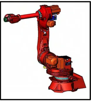
2.1 SMART NS 12-1.85, COMAU Articulated Robot 6
2.2 SMART NS 16-1.65, COMAU Articulated Robot 7
2.3 Characteristics and Performance of the SMART NS Robots 8
2.4 SMART NS 16-1.65 working envelope 9
2.5 Top and side view of operating areas and overall dimension of 10 SMART NS 16-1.65
2.6 Front view of operating areas and overall dimension of 11 SMART NS 16- 1.65
2.7 Top and side view of operating areas and overall dimension of 12 SMART NS 12-1.85
2.8 Front view of operating areas and overall dimension of 13 SMART NS 16- 1.65
2.9 A Robot’s Work Envelope 14
2.10 Robot Operation Hazards 19
2.11 Safety Zones 22
2.12 Equation for double robots 23
3.1 Flow Chart of Project Design 31
3.2 Examples of Safety Relays 32
3.3 Types of Light Curtains/Grids 33
3.4 Application examples of sensor 35
3.5 System set up for Emergency Stop 36
3.6 Door Components 37
3.7 Design 1 38
x
4.1 Risk estimation 45
4.2 Solid Model of Safety System Design 47
4.3 Safety Floor Marking 51
4.4 Safety Guard 54
4.5 Door with Pole 54
4.6 Safety Interlock Switch (When Door Opened) 55
4.7 Safety Interlock Switch (When Door Closed) 55
4.8 Safety Interlock Switch (Female) 56
xi
LIST OF ABBREVIATIONS, SYMBOLS AND
NOMENCLATURE
COMAU - COnsorsio Machine Utensil
CAD - Computer-Aided Design
CNC - Computer Numerical Method
CATIA - Computer Aided Three-Dimensional Interactive Application
3D - Third Dimension
ANSI - American National Standards Institute
ISO - International Organization for Standardization RIA - Robotic Industries Association
1 hardware; it includes any devices interfaced to the robot to manipulate of the work cell. Each new field and application may call for particular precautions for operators, maintenance workers, robot systems, and so on. Both manufacturers and users did not receive a lot attention about robot safety in the previous. This situation is converting over the last few years, which is an accident of robot could be one of the parameters. In fact, safety standards for industrial robots are under discussion in several countries, and the International Organization for Standardization (ISO) has already used a lot of work in this direction. (B. S. Dhillon, 1991).
2
1.2 Problem statement
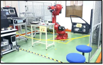
The problem of the existing COMAU Articulated Robot is that the safety system is not fully protect the users or people from being injured by the robot. It can be dangerous to the users and becoming a problem with the robot for performing tasks. This is a serious situation where to solve this problem, a fully protected safety system need to be designed to protect robot users that nearby the workspace.
Figure 1.1 : The workspace area of COMAU Articulated Robot in Robotics Laboratory, UTeM.
1.2Objectives
i. To design a safety system for the COMAU Articulated Robot.
3
1.3Scope of the Project
a) To design a safety system for COMAU Articulated Robot based on several criterias in order to meet the following requirements:
i. To safeguard the robot operator, robot maintenance staff and visitors.
ii. To safeguard the robot from being damaged in the case of accident.
4
CHAPTER 2
LITERATURE REVIEW
2.1 Introduction
There are many condition where the robot accidents can happen, such as through in programming, program touch-up, services, repairing, setup, examining, or modifying. During these operations, the related person such as the operator, a programmer, or maintenance personnel may be injured if they are working within the robot's working envelope (OSHA, 1999). Safety results from a detailed plan to operate in a secure way; as a result, safety consideration must be part of every machine and work-cell design. Introduction of safe robot operating procedures is very important at the start of any robot study.
5
In all aspects in safety of machine, involving robot programming, the following ranking approach should be applied:
a) Obseve the hazards
b) The hazards that cannot be planned away is offered
c) Making use of the personal protective equipment, training, and employment
of the safety system in order to lower the residual risks.
2.2 COMAU Robots
The SMART NS robots in the case study are from the COMAU family of robots that are plotted to linear applications.
The main robot characteristics are listed below:
i) Pre-engineered for determination with a sort of optional devices; ii) All reducers are oil lubricated, except axis 6, where lubricating grease
is put on rather;
iii) The option of linking electrical and pneumatic services to the forearm; iv) Decreased wrist proportions enable high capacity, orientation in small
distances;
v) Large work area, received by bringing axis 2 forward in intercourse to axis 1;
vi) High repeatability;
vii) Stage of security (IP67 for the wrist body and IP65 for the rest of the robot);
viii) No particular devices for axis recompense.
6
The vital robot fittings involved:
i. An appropriate welding dressing;
ii. An internal pneumatic line with upper association on the back of the forearm;
iii. Wiring that incorporates a service line with a connector on the upper plate next to the pneumatic connection;
iv. Flat surfaces and threaded holes on the upper part of the forearm that can be used to gather fixtures;
SMART NS robots covers various type of aspects in order to suit the application demands. COMAU Robot that involved in this case study are SMART NS 12-1.85 and SMART NS 16-1.65 as shown in Figure 2.1 and Figure 2.2.
7
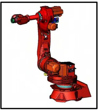
Figure 2.2 : SMART NS 16-1.65, COMAU Articulated Robot (COMAU Robot Manual, 2005)
There are several features of COMAU robot such as payload, working envelope and reachable area which are different in certain conditions but it is proved that they are typically same based on the similar functioning rules.
Table 2.1 shows the available versions of SMART NS robots.
Table 2.1 : SMART NS Version Available (COMAU Robot Manual, 2005)
Version Payload Reach
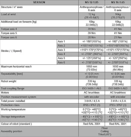
8 2.2.1 Technical Characteristics
Figure 2.3 shows the characteristics and performance of the SMART NS robots.
Figure 2.3 : Characteristics and Performance of the SMART NS Robots (COMAU Robot Manual,
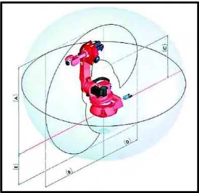
9 2.2.2 Working Envelope of SMART NS 16-1.65
Figure 2.4 shows the working envelope of SMART NS 16-1.65 robot, with the values of A= 1.951 mm, B= 1.651 mm, C= 950 mm, D= 957 mm, E= 685 mm.
10
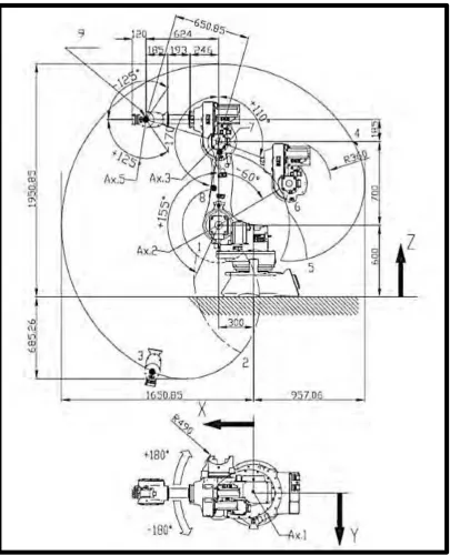
2.2.3 Operating Areas and Robot Overall Dimensions
Figure 2.5 and Figure 2.6 shows the operating areas and overall dimension of SMART NS 16-1.65 from the top view, front view and side view.
Figure 2.5 : Top and side view of operating areas and overall dimension of SMART NS 16-1.65