UNIVERSITI TEKNIKAL MALAYSIA MELAKA
ROBOT COMAU PROGRAMMING FOR COMPLEX PATH
This report submitted in accordance with requirement of the Universiti Teknikal Malaysia Melaka (UTeM) for the Bachelor Degree of Manufacturing Engineering
(Robotic and Automation) with Honours.
By
ZALINA BINTI ABU LUKMAN
DECLARATION
I hereby, declared this report entitled “Robot Comau Programming for Complex Path” is the results of my own research except as cited in references.
Signature : ……….
Author’s Name : Zalina Binti Abu Lukman
APPROVAL
This report is submitted to the Faculty of Manufacturing Engineering of UTEM as a partial fulfillment of the requirements for the degree of Bachelor of Manufacturing Engineering (Robotic and Automation) with Honours. The members of the supervisory committee are as follow:
APPROVAL
This report is submitted to the Faculty of Manufacturing Engineering of UTEM as a partial fulfillment of the requirements for the degree of Bachelor of Manufacturing Engineering (Robotic and Automation) with Honours. The members of the supervisory committee are as follow:
ABSTRACT
ABSTRAK
DEDICATION
F or m y b e lov e d p a r e n t s
Abu Lukman Bin Haji Ismail
Razali Bin Hussien
Fatimah Bt. Yahya
A n d f or m y sp e c i a l p e r son a n d f r i e n d s
En. Khairol Anuar Bin Rakiman
Nur Anis Bt. A. Rahman
ACKNOWLEDGEMENT
First of all, Syukur Alhamdulillah and all praises to Allah S.W.T which lead me to accomplish this Final Year Project (Semester 1) – Projek Sarjana Muda in a course of BMFG 4913. I would like to express my big appreciation and deepest gratitude from the bottom of my heart to my supervisor, En. Khairol Anuar Bin Rakiman and also to my examiner, En. Ruzaidi Bin Zamri for their encouragement, ideas, support, and inspiration and for their irreplaceable unfailing patience, guidance throughout this project report. Their knowledge and experience really inspired and spurred myself.
Special thanks also to technician lab members and whom those involve in completing this projects who have been helping together to give idea and any flourishing suggestions, a special thanks for their sincerely and co-operations. Also big thanks for my family as well as friends without their wise council and dependable assistance this project research would not have been possible. Last but not least. all my friends and peers who are good companions in times of need and give a lot of support to me.
Thank you, very much.
Wassalam.
TABLE OF CONTENTS
1.2 Problem Statement 1.3 Objectives1.4 Scope of the Project
2. LITERATURE REVIEW
2.1 Evidence of Programming Robot for Complex Path 2.2 Programming Robot
2.3 Theory of Path Planning
2.4 Programming Using Workspace 2.5 Analysis
2.5.1 Forward Kinematics Analysis
2.5.2 Forward and Inverse Kinematics of the Teach-Robot 2.5.3 A Survey of Robot Programming Systems
3. METHODOLOGY 3.1 Path Planning
3.2 Off-line Programming 3.3 Integration of Simulation 3.4 Methodology Conclusion 3.4.1 Trajectory Path Planning 3.4.2 Sketching Path
3.4.3 Mathematical Calculation 3.4.3.1 Workspace Layout 3.4.4 Plotting Graph
3.4.5 Research on Complex Path with Inverse Kinematic, & Robot Performance in Accuracy of Robot Position, and Programming
Comau Robot Language
4. SIMULATION PREPARATION 4.1 Path Planning
4.1.1 Robot Manipulator Angle Movement
4.1.2 Trajectory Planning with Polynomial Via Points 4.1.2.1 Mathematical Model for Trajectory Polynomial 4.1.2.2 Plotting Graph Using Matlab
4.2 Workspace Layout 4.3 Conclusion
5. RESULT & DISCUSSION ON COMPLEX PATH ANALYSIS 5.1 Result
5.1.1 Design complex engineering part 5.1.1.1Chassis
5.1.1.2 Worktable
5.1.1.3 Screw Part Feeder
5.1.2 Robot Simulation Programming Task 5.1.2.1 Robot Simulation
5.1.2.2 Generating Programming Code 5.1.2.3 Dry Run Simulation
5.2 Discussion on Complex Path Analysis 5.2.1 Path Planning
5.2.2 Geometry Point (GP) 5.2.3 Programming Language 5.2.4 Robot Position Accuracy 5.2.5 Motion
5.2.5.1 Inverse Kinematic
6. CONCLUSION, & RECOMMENDATION 6.1 Conclusion
6.2 Recommendation
REFERENCES
APPENDICES
A Technical Specification of Comau Robot
B The Workspace Area of Comau Robot Smart NS 16-1.65
C The Schematic Diagram That Showing Detail about the Axes Stroke of the Comau Robot Hand (Comau Robotics)
D Design Engineering Part Drawing (Chassis) E Design Engineering Part Drawing (Worktable)
F Design Engineering Part Drawing (Screw Part Feeder)
G Design Engineering Part Drawing (Assembling Chassis & Worktable) H Robot Simulation with 30 Geometry Point
J Robot Simulation In Workspace 5TM Software For Complex Path K Generated Programming Code of Robot Simulation Path in Workspace
5TM Software
L Comau Robot Teach Pendant & Equipments for Dry Run Simulation M Path Flow of Dry Run Simulation For Real Comau Robot Application N Modifying, Translate Programming Code Generated Using WinC4G
Software
LIST OF TABLES
2.1 Structure and motion parameters of the motor 13
LIST OF FIGURES
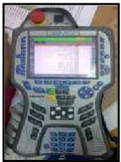
1.1 A teach Pendant 3
2.1 A water pump to be deburred (the marked line shows the desired deburring path)
5
2.2 Water pump deburring cell setup 5
2.3 Pictures taken while the tool is in force control mode and Programmed to follow the edge of the water pump
6
2.4 Guiding path (left) and recorded path (right) 6 2.5 Human interface concept for interactive robot operation 10
2.6 Example of work space model 11
2.7 Structure of motion schema and its interaction with work space model
11
2.8 Kinematics model and coordinate frames of the motor 13
2.9 A diagram of Teach-Robot 15
3.1 A Methodology flow chart of the project 19
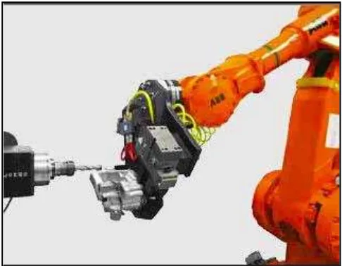
4.1 KUKA robot in automatic insertion of screws process in plastic vehicle members
22
4.2 The sketches of robot manipulator angle movement 23
4.3(a) Graph angular position versus time 29
4.3(b) Graph velocity versus time 29
4.3(c) Graph acceleration versus time 30
4.4(a) Graph angular position versus time 30
4.4(b) Graph velocity versus time 31
4.4(c) Graph acceleration versus time 31
4.5(a) Loading Comau robot into workspace 32
briefly teaching the robot in screw inserting process
5.1 Import CAD design model into Workspace 5TM Software 36 5.2 Chassis (Engineering Part) as major part to insert screw 36 5.3 Worktable to hold the chassis during screw insertion process 37 5.4 A screw part feeder used to supply screw to the robot 37 5.5 A CAD model that will be load into Workspace 5 TM Software as
worktable hold chassis to make the robot insert screw on it
38
5.6 Path Planning Created (inserting screw point on car part) 40 5.7(a) Pendant used to move the robot and GP point will be created 41
5.7(b) GP Properties Box to modifying the GP 42
5.7(c) The sequences of the GP created and the explanation of repeated GP
43
5.8 Comau software used to integrate robot programming 44 5.9(a) A sign show the complex path programming successfully
transferred
46
5.9(b) Complex path program in teach pendant and ready to dry run simulation
46
5.9(c) The image of robot show that Comau Robot starts to move to the desired location
46
5.10(a) The work envelope of real Comau Robot NS16 48 5.10(b) The maximum horizontal reach of real Comau Robot NS16 is
1650mm
48
5.10(c) The maximum horizontal reach of Comau Robot NS16 in Workspace 5TM Software is 1739 mm which longer than real Comau Robot
49
5.11 The calibrated position (home position) of Comau Robot 52 5.12 Six joint values obtained for the robot position at GP0005 55
LIST OF ABBREVIATIONS
DOF - Degree of Freedom GP - Geometry Point
CAD - Computer Aided Design D-H - Denavit Hartenberg
CHAPTER 1
INTRODUCTION
This chapter is describing about the history of the robot, the basic programming used for robot programming, the application of the robot in the industry. Besides, in this chapter, there are also briefly defined the problem statement involve in this project, the objectives, the scope of the project, and the project outline.
1.1 Background
In the twenty-first century, robots have come to be known by everyone. However, the term robot was first introduced to our vocabulary just a few decades ago. The word originated from the Czech word robot, which means ‘slave laborer’. Isaac Asimov (1940) coin the term robotics in his short science fiction in which he defined robotics as a study of robots. In 1988, the word robotics was including in the Webster’s New World Dictionary. As basically known, robot is a combination of motors, sensors, mechanical parts and software. Although the word has many different definitions as seen in different dictionaries and encyclopedias, the Robot Institute of America may reflect main features of modern robot systems in which a robot is a reprogrammable multifunctional manipulator designed to move material, parts, tools, or specialized devices though variable programmable motion of the performance of variety of tasks. George C. Devol (1953) develops the first robot and further George Devol JR. (1954) applies for a patent for a programmable transfer device.
robot programming is to teach these actions to the robot. There are two basic categories of greatest commercial importances nowadays are lead through programming, and textual language programming. Lead through programming consists of forcing the robot arm to move through the required motion sequences and recording the motion into the controller memory. Moreover, lead through method is used to program playback robot. In the case of point playbacks robots, the usual procedure is to use a control box which called as a teach pendent to drive the robot joints to each of desired point in the workspaces, and record the point into memory for subsequent playback. Textual programming method uses an English-like language to establish the logic and sequence of the work cycle. A computer terminal is used to input the program instructions into the controller but a teach pendant is also used to define the locations of the various points in the workspace. The robot programming language names the point as symbols in the program and these symbols are subsequently defined by showing the robot their locations. In addition to identifying points in the workspace, the robot language permit the use of calculations, more detailed logic flow, and subroutines in the programs, and greater use of sensors and communications. Accordingly, the use if the textual language corresponds largely to the so called intelligent robots.
Figure 1.1: A teach Pendant
1.2 Problem Statement
In this project, finding the programming code in off-line programming for complex path, and analyzing the motion path planning of the robot has need to be done. The suitable language code of robot programming and the software involving in this project need to be explored and learn. The most important, the robot programming has to simulate with the robot as dry run for complex engineering part that has been identified as an imagination product in simulation.
1.3 Objectives
The primary objectives of this project are:
a. To integrate robot programming into real application (dry run). b. To determine the accuracy of robot position by simulation. c. To analyze the robot motion for complex path.
1.4 Scope of The Project
There are several scopes that focused on this project: a. To study the theory of motion planning.
b. To identify the complex engineering part to be the product for programming. c. To explore and learn the related software involve in this project.
d. To generate the suitable code for programming language and transfer into real simulation.
CHAPTER 2
LITERATURE REVIEW
This chapter will describe about the past researches review that related to the project. From Oxford Advanced Genie dictionary, Literature means the pieces of writing or printed information on a particular subject. This literature review is important to make this project relate with the past researches and for the next chapter.
Before proceed in the detail about the researches theory and information that related to the project, its better we see first the evidence overall past researches about programming robot for complex path. In this project, we use off line programming without using online programming. Robot Institute of America (1979) defines a robot is a reprogrammable, multifunctional manipulator designed to move material, parts, tools or specialized devices through variable programmed motions for the performance of a variety of tasks.
2.1 Evidence of Programming Robot for Complex Path
system in industrial settings. Figure 2.1 shows a water pump cast that needs to be deburred around its edge in a cell shown in Figure 2.2. As can be seen, the edge is a complicated 3D contour that requires the deburring tool change its orientation and depth at different parts of the contour. Programming this contour took the system integrator almost one week using a position controlled robot and joystick teaching. The force control assisted path generation system cut this time to half hour, most of which is spent on teaching the guiding path. Contour following and path program generation takes less than 1 minute. Figure 2.3 shows the contour following in action. The guiding path has 66 points. After the contour following and the real-time path recording with line recovery, the final path contains 454 points (Figure 2.4).
Figure 2.1: A water pump to be deburred (the marked line shows the desired deburring path). The
side (left) and front (right) views are shown as one of the complex part that is need to be program (George, Z. et. al: (2008).
Figure 2.3: Pictures taken while the tool is in force control mode and programmed to follow the
edge of the water pump (George, Z. et. al: (2008).
Figure 2.4: Guiding path (left) and recorded path (right) (George, Z. et. al: (2008).
number of guiding points in order for the contour following to be executed at a reasonable speed. Obviously this approach chooses simplicity and economy over the full autonomy provided by some hybrid force/vision approaches. Because this system is intended for industrial usage, this approach is justifiable. Real life applications and customer feedback have confirmed the effectiveness of the presented system.
Stocco, P. et al: (2008) have made a research on the optimization of real time complex path generation in constrained intelligent motion applications based on IPM motor drives. The improvements in the constrained real-time path generation for high performance motion control systems are presented in this paper.
2.2 Programming Robot