International Journal of Soft Computing and Engineering (IJSCE) ISSN: 2231-2307, Volume-2, Issue-1, March 2012
470
Abstract—Fire fighting is risky profession. They are not only extinguishing fires in tall buildings but also must drag heavy hoses, climb high ladders and carry people from buildings and other situations. There are many fire fighters lost their lives in the line of duty each year throughout the world. The statistics of the fire fighter fatalities are still maintain at high level every year and it may continue to increase if there is no improvement in fire fighting techniques and technology. The paper describes the water pressure loss analysis of mobile fire fighting machine prototype.
Index Terms— Fire Fighting, Mobile Machine, Pressure Loss Analysis.
I. INTRODUCTION
Fire fighter need to work in a long and irregular hours and unfriendly working environment such as high temperature, dusty and low humidity, firefighters are also facing with potentially life threatening situation such as explosion, collapsed building and radioactive. The common equipment used by firefighters such as flat head axe, halligan bar, turnout jacket, fire retardant or bunker pants, boots, flashlight, helmet, face mask, and gloves do not significantly reduce risk on their lives when facing those life threatening situations
.
In the USA, the traumatic death rate amongst firefighters shows that 1.9 firefighters are killed per year, per 100,000 structure fires which is the rate only slightly lower than that obtained in the early 1980s [1] . However, this rate was increasing to 3.0 per 100,000 structure fires across a thirty year period which is peaking in the 1990s [2]. There are many causes for Line of Duty Deaths (LODD) such as smoke inhalation, burns, crushing injuries and related trauma [3]. As a result of this, over the past few years, research and development on firefighting technology is extensively made around the world especially in US, Japan, and a number of European companies. There were many studies [4-8] had emphasized on machine development to replace fire fighter to fight fire in dangerous situations and to reduce the fire fighter risk. The machines help the fire fighter using extinguishing agent such as water, foam or others without fire fighter having to set up or operate directly in danger areas.
Manuscript received February 7, 2011.
CheeFai Tan, PhD, Mechanical Engineering Department, Universiti Teknikal Malaysia Melaka, Hang Tuah Jaya, Melaka, Malaysia, +60623-46710, ([email protected]).
Ranjit Singh Sarban Singh, Computer Engineering Department, Universiti Teknikal Malaysia Melaka, Hang Tuah Jaya, Melaka, Malaysia, +606-5552161/+60125541369, ([email protected]).
Mohd. Rizal Alkahari, Mechanical Engineering Department, Universiti Teknikal Malaysia Melaka, Hang Tuah Jaya, Melaka, Malaysia, ([email protected]).
Amano [9] highlighted the weaknesses of existing machine design and suggest integration of all important elements in developing fire fighting machine so that a successful rescuing process can be achieved. These elements are size, weight, cost and performance. Therefore, this research was integrated required technical aspects to develop a mobile machine based on the end user requirements which is fire fighting rescue team. The paper describes the water pressure loss analysis of the developed fire fighting machine (FFM).
II.CONTROL SYSTEM
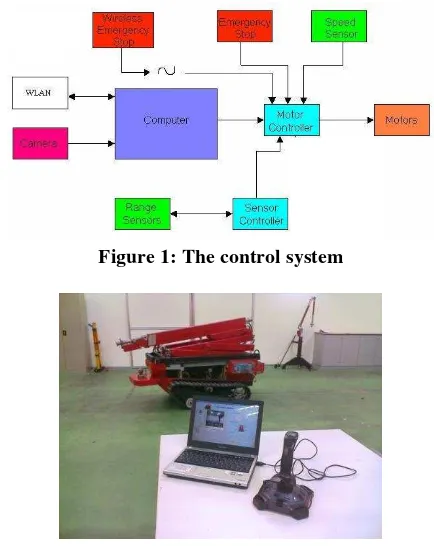
The developed prototype is a mobile fire fighting machine that can be controlled wirelessly via mobile computer. Therefore, special dedicated software is developed in order to interface the machine and the computer. Additional control mechanism is added by integrating the system with a joystick in order to ensure the mobility control can be improved. Figure 1 shows the control system of FFM. Visual Basic Programming language is used in the development of the program that interfaces the machine with computer. Two way communication also possible between the victim in the fire ground and the machine operator as there is internal microphone integrated with the system. Figure 2 shows the machine and its controller which is a mobile computer and a joystick attached to the computer.
Figure 1: The control system
Figure 2: Controller and FFM
Water Pressure Loss Analysis of
Mobile Machine for Fire Fighting Purpose
Off-Grid System for House Car Pouch Lighting
471
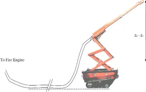
The developed FFM as shown in Figure 3 and the
general specification as shown in Table 1.
Figure 3: The FFM prototype
Table 1: General specification of FFM
III. DESIGN ANALYSIS
The engineering design analysis is conducted on the structure of the FFM in order to ensure its reliability to withstand the load experienced during operation. As water is projected from a nozzle to form a „jet‟ or fire fighting stream, the nozzle tends to recoil in the opposite direction. Therefore, it is essential to counter the hose nozzle reactive force generated during fire fighting process. Manual calculation and computer aided engineering software utilizing Finite element analysis is applied in the study. Analysis made consider the maximum load applied on the machine and the maximum water pressure experienced by the machine during operation. Calculation made is to check the stability of the machine when the machine is in use.
Computer Aided Engineering (CAE) and design optimization is becoming more crucial in modern engineering design. It is because it applies numerical techniques to engineering systems in order to assist the engineering designers. This approach will be useful in improving the system's performance, weight, reliability, and/or cost
.
CAE analysis and optimization methodologies can be applied during the product development stage to ensure that the finished design will have the high performance, high reliability, low weight, and/or low cost. Alternatively, design optimization methods can also be applied to existing products to identify potential design improvements. In the study, two
types of design optimization being performed; namely structural design optimization and product design for assembly optimization using Boothroyd Dewhurst Method.
After completing design analysis, the prototype fabrication of the FFM proceeded. The prototype produced is a full scale prototype.
IV. PRESSURE LOSS ANALYSIS
i) Pressure Loss through Hose and Height
During operation, Pressure loss is a term used to describe the decrease in pressure from one point in a tube or hose to another point downstream. The importance of pressure loss analysis has been highlighted by many authors [10-14]. Pressure drop is the result of frictional forces on the fluid as it flows through the hose. The frictional forces are caused by a resistance to flow. However, the increase of height at the exit of flow will also cause loss of pressure. Figure 4 shows the schematic of pressure loss factor. In determining the pressure
loss, Bernoulli‟s equation is used.
Figure 4: Pressure loss due to hose length and height
Bernoulli Principle which relates pressure, velocity and elevation between two points in flow field is applied. Assumption made using the principle is the flow is steady, incompressible, irrotational and nonviscous. The following formula is used in Fire and Rescue Department.
EP = NP + FLHose + FLAppliance + PElevation (1) Where,
EP = Engine Pressure NP = Nozzle Pressure
FLHose = Friction Loss in the fire hose FLAppliance = Friction Loss in the appliance
PElevation = Pressure loss or gain due to elevation
Based on Manual of Firemanship Book 7: Hydraulics, pumps and pump operation, the Friction loss occur in fire hose. The friction loss is a function of hose diameter, hose length, discharge volume any appliance used such as wyes or monitors used in the hose layout. The basic of calculation in fire hydraulic revolves around three fundamental hydraulic
principles namely, Bernoulli‟s Equation, Darcy-Weibach
Equation and Continuity Equation. Friction Loss Formula as given in Equation (4.1) is derived from these three basic equations.
International Journal of Soft Computing and Engineering (IJSCE) ISSN: 2231-2307, Volume-2, Issue-1, March 2012
472 FLHose = CQ2L (2)
Where,
FL = friction loss (expressed in psi) C = coefficient of friction
Q = flow rate in hundreds of gallons (gpm/100) L = Length of hose in hundreds of feet (L/100)
Based on Bernoulli‟s equation, it is given that:
FL V gz
P V gz
P1 1 12 2 2 22
2 1 2
1
(3)Where,
P
= Pressure
= Fluid densityg
= Gravityz
= HeightV
= Fluid velocityf
h
= Friction lossesWhereas based on Continuity equation, it is known that:
2 2 1
1
V
A
V
A
Q
(4)Where,
Q
= Volume flow rateA
= Cross section areaV
= Fluid velocityii) Nozzle Force
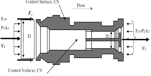
In analyzing force at nozzle of FFM, the system can be considered as a thermodynamic system that has an open system or control volume and involves the flow of fluid through the fix volume. As fluid moves through the control volume, the mass entering the control volume is equal to the mass leaving the control volume. The surface enclosing the control volume is referred to as the control surface. The force at nozzle is determined with information such as, maximum
water pressure and nozzle dimension using Bernoulli‟s
equation and momentum equation. The component involve in the force determination of the nozzle as shown in Figure 5.
Figure 5: Cross sectional view of water nozzle The water inlet and outlet velocity
V
1 andV
2 can be obtained by solving Continuity Equation.1
V
1
A
Q
21
4
D
Q
(5)
Based on the Friction Loss, the Nozzle Pressure can be calculated based on the following formula. (Referring to NFPA 1002 Standard of Fire Apparatus Driver/Operator Profesional Qualifications)
EP = NP + FLHose + FLAppliance + PElevation (6)
V. RESULTS
iii)Pressure Loss through Hose and Height Flow rate, Q2 = V2A2
= 629.257 gpm
Therefore, Friction Loss is
FL = 0.00065V2 2
= 1.399 kPa
Based on the Friction Loss, the Nozzle Pressure can be calculated based on the following formula.
NP = 11.64 bar
5.2 Nozzle Force
For, D1=0.0635m, D2 = 0.03302m,
Q
=1 3
0397
.
0
m
s
,the water inlet and outlet velocity V1 and V2 obtained by solving Continuity Equation.
1
V
1
A Q
2
1
4
D Q
1
53
.
12
ms
2
V
2
A Q
2
2 4
D Q
1
36
.
46
ms
Based on the Friction Loss, the Nozzle Pressure can be calculated based on the following formula.
NP = EP - FLHose - FLAppliance + PElevation = 11.64 bar
Bernoulli‟s Momentum equation is used to determine the
force,
F
nozzle, required to hold the nozzle in it position.
V2 V1
P1A1 P2A2Q
Fnozzle
2,257NTherefore the nozzle reaction force or minimum force required to hold the nozzle is 2.257 N.
VI. CONCLUSION
In this paper, the pressure loss of nozzle and nozzle force has been analyzed. Three fundamental hydraulic principles
were used to analyze the nozzle, namely, Bernoulli‟s
Off-Grid System for House Car Pouch Lighting
473 ACKNOWLEDGMENT
We would like to thank the management, academic, administration and technical staffs who have involved either directly or indirectly in this study. Appreciation also goes to Mr Liew Sow Ming of Ritz Power Mechanics Sdn Bhd, UTeM and Ministry of Technology Science and Innovation (MOSTI) who have providing financial assistance to carry out the research.
Special acknowledgement is also dedicated to laboratory staffs of Mechanical Engineering Faculty, Universiti Teknikal Malaysia Melaka, and Malacca Fire and Rescue Department for their support and help during this project.
REFERENCES
[1] International Association of Fire Fighters (IAFF), 2000, “Death and
Injury Survey, Washington,” Available from: http://www.iaff.org/ HS/PDF/ 2000%20D&I.pdf. Accessed on 5th September 2008. [2] Kyle, S.N. 2007, “NFPA Releases Firefighter Death Study, U.S.A,”
Available from: http://cms.firehouse.com/content/section/news. Accessed on 5th September 2008.
[3] Rosmuller, N. and Ale, B.J.M., “Classification of fatal firefighter accidents in the Netherlands: Time pressure and aim of the suppression activity,” Journal of Safety Science, No. 46, 2008, pp. 282 –290. [4] Shanghai Qiangshi Fire-fighting Equipment Co. Ltd., 2007, “Qiangshi
Fire Fighting Robot, China,” Available from: www.qs119.com/en/ showpro.asp?id=530. Accessed on 5th September 2008.
[5] Sofge, E. 2007, “First Firefighting Robots Deployed, Could Spark Autonomous Dept. Las Vegas,” Available from: http://www.popularmechanics.com/science/roboticsl. Accessed on 5th September 2008.
[6] Konda, A. “The Fire Fighting Snake Robot. Europe,” Available from: http://www.sintef.com. Accessed on 4th September 2008.
[7] HKFSD, “Mobile Fire Fighting Supporting Machine LUF 60R.
China,” Available from: http://www.hkfsd.gov.hk/home/images/ equipment/fire/e_luf60.html. Accessed on 13th September 2008.
[8] NEVA, “Mobile Fire Fighting Robot. Russia,” Available from:
http://www.neva.ru/CNII-RTC/Firemen/html. Accessed on 13th September 2008.
[9] Amano, H. “Present Status and Problems of Fire Fighting Robots,” SICE 2002.Proceedings of the 41st SICE Annual Conference, Vol. 2, 2002, page 880- 885.
[10] Manual of Firemanship Book 7: Hydraulics, pumps and pump operation, Second Edition, Home Office, Fire Policy Unit, United Kingdom. February 1987.
[11] Sturtevant, T.B. “Introduction to Fire Pump Operations”, 2nd Edition, Thompson Delmar Learning Publishing, 2004.
[12] Fire Protection Handbook, 19th Edition, Volume 1, National Fire Protection Association, 2003
[13] Cote, A.E. “Organizing for Fire and Rescue Services”, Jones & Bartlett Publishers; 1st Edition, Jan. 2003
[14] Kemmpler, J. “Fire Fighting Pump and Operation,” Lecture Notes, http://home.honolulu.hawaii.edu/ ~jkemmler/chapter6.htm. Accessed on 13th September 2009.
CheeFai Tan, PhD, graduated in Mechanical Engineering with honours, Master of Science in Manufacturing Systems Engineering from Universiti Putra Malaysia and PhD in Industrial Design Engineering from Eindhoven University of Technology, the Netherlands. He is a Senior Lecturer at Department of Design & Innovation, Faculty of Mechanical Engineering, Universiti Teknikal Malaysia Melaka since 2003. He actively involved in teaching and learning, consultation as well as research and development activities. Ir. Dr. Tan has published over 80 papers in referred conferences, book chapter and journals. His research interests cover the aspects of mechanical engineering design, industrial design, smart
system, multidisciplinary design and human-technology interaction design.
Ranjit Singh Sarban Singh received his Diploma of Technology Computer (Electronics Engineering) from Politeknik Seberang Perai, Malaysia in 2003. He then graduated with a Bachelor Degree in Electronics Engineering (Computer Engineering) from KUTKM Malaysia in 2006 and received his Master of Science Engineering from Multimedia University, Melaka Malaysia. His keen interest is in image processing motion estimation, solar system application and electronics applications. Besides that, the author is involved in the development of motion estimation algorithm application, actively involved in smart consumer electronics applications and design and development solar systems.