iv
ACKNOWLEDGEMENT
First of all, thanks to ALLAH S.W.T for his mercy and guidance in giving me full strength to complete this report. Many thank to my supervisor, Dr. Mohd Yusoff Bin Sulaiman for his support, guidance and advice me in completing this project. I will never forget his kindness in helping me since my first day. He also gives me full of support and advice.
I am most grateful to my parents. They have always loved me and supported my every choice. I’m also thankful for the great joys and happiness brought to me by my others sisters and brothers.
I also would like to express greatest thankfulness and appreciation to all the lecturers and technicians of Mechanical Engineering Faculty for giving me their cooperation and help in order to complete this project.
v
ABSTRACT
Wave is caused by the wind blowing over the surface of the ocean. In many areas of the world, the wind blow with enough consistency and force to provide continues waves. There is tremendous energy in the ocean waves. Wave power devices extract energy directly from the surface motion of ocean waves or from pressure fluctuations below the surface. Wave technologies have been design to be installed in nearshore, offshore, and far offshore locations. The oscillating water column system is a form of terminator in which water enters through a subsurface opening into a chamber with air trapped above it. The wave action causes the captured water column to move up and down like a piston to force the air through an opening connected to a turbine. This report described a project to scale model of a wave energy machine. This machine is used to convert wave energy into electrical energy. Furthermore, this report described about the conversion of wave energy. Wave energy Mechanical energy Electrical energy
vi
ABSTRAK
Ombak adalah disebabkan oleh tiupan angin di atas permukaan laut. Di kebanyakan kawasan di dunia, tiupan angin yang konsisten dan kuasa yang mencukupi membolehkan ombak yang berterusan. Ombak lautan mempunyai tenaga yang terlalu hebat. Alatan kuasa ombak mengasingkan tenaga terus dari pergerakan permukaan pada ombak lautan atau dari tekanan boleh-ubah di bawah permukaan. Teknologi ombak telah direka untuk dipasangkan di berdekatan tebing, di bawah tebing, dan di bawah tebing yang jauh. Sistem air berayun turus (OWC) ialah satu bentuk penamat di mana air akan memasuki melalui di bawah permukaan yang terbuka ke dalam ruang di mana terdapat udara terperangkap di atasnya. Tindakan ombak menyebabkan kolum air yang terperangkap untuk bergerak ke atas dan ke bawah sama seperti omboh untuk memaksa udara melalui sambungan terbuka ke turbin. Laporan ini menghuraikan satu projek untuk menjadi ganti ukuran sebenar model kepada satu mesin tenaga ombak. Mesin ini digunakan untuk menukarkan tenaga ombak kepada tenaga elektrik. Seterusnya, laporan ini menghuraikan tentang penukaran terhadap tenaga ombak.
Tenaga ombak Tenaga mekanikal Tenaga elektrik
LIST OF CONTENTS
CHAPTER TITLE PAGE
DECLARATION ii
ACKNOWLEDGEMENT iii
ABSTRACT iv
LIST OF CONTENTS vi
LIST OF TABLE viii
LIST OF FIGURE ix
LIST OF SYMBOL x
LIST OF APPENDICE xi
CHAPTER 1 INTRODUCTION
1.1 Project Background 1
1.2 Objective 1
1.3 Problem Statement 1
1.4 Scope 2
CHAPTER 2 LITERATURE STUDY
2.1 Physical Concepts 3
2.1.1 Wave Power Formula 4
2.1.2 Wave Energy and Wave Energy Flux 5
2.2 Modern Technology 6
2.2.1 The Technology – Shoreline Devices 6 2.2.2 The Technology - Offshore Devices 9
CHAPTER 3 METHODOLOGY 3.1 Flowchart
3.1.1 Flowchart for PSM 1 14
3.1.2 Flowchart for PSM 2 15 3.2 Measuring the wave force 15
3.3 Measuring the wave height 16
3.4 Calculation 16
3.5 Fabrication progress 17
3.5.1 The wave tank 17
3.5.2 The wave energy machine 19
CHAPTER 4 EXPECTED RESULT AND DISCUSSION
4.1 Result 24
4.2 Discussion 25
CHAPTER 5 CONCLUSION AND RECOMMENDITION 26
REFERENCE 27
viii
LIST OF TABLE
NO. TITLE PAGE
3.5.1 Wave tank specification 17
3.5.2 Wave energy machine specification 19
4.1 Water depth test 24
ix
LIST OF FIGURE
NUMBER TITLE PAGE
2.1 Diagram Shoreline Wave Energy Devices 8
2.2 Diagram Representative Offshore Wave 10
Energy Device 2.3 Pelamis Wave Energy Converter 11
2.4 Wave Dragon 12
3.1 Flowchart for PSM 1 14
3.2 Flowchart for PSM 2 15
3.5.1 Wave Tank 18
3.5.2.1 Fan Blade 20
3.5.2.2 Coupling 20
3.5.2.3 Fabricated aluminium rod to joint fan blade 21
x
LIST OF SYMBOL
P = Wave energy flux per unit wave crest length, kW/m Hm0 = Significant wave height, m
T = Wave period, s
ρ = Mass density of the water, kg/m3 g = Acceleration by gravity, m/s2
E = Mean wave energy density per unit horizontal area, J/m2 cg = The group velocity, m/s
λ = Wavelength, m
k = Spring constant
m = Wave mass, kg
ρ = Water density
W = Water width, m h = Wave height, m
ω = Wave frequency, rad/sec
xi
LIST OF APPENDICE
NUMBER TITLE PAGE
A Picture Machine on the sea 29
B Picture Machine inside the wave tank 30
C Machine Assembly 31
D Gantt Chart PSM 1 32
1
CHAPTER 1
INTRODUCTION
1.1 Project Background
This project is focusing on demonstrating the working principal of energy conversion. A small model of a wave energy machine will be fabricate and test. The wave theories will be applied to this machine and use to estimate the energy conversion.
1.2 Objective
To demonstrated the working principal of energy conversion.
1.3 Problem statements
These are problem statements to deploying wave power devices:
2 Constructing devices that can survive saltwater corrosion; likely sources of failure include seized bearings, broken welds, and snapped mooring lines. Knowing this, this project will create prototypes that are so overbuilt that materials costs prohibit affordable production.
1.4 Scope
The scope of this project is:
3
CHAPTER 2
LITERATURE STUDY
Wave power is the transport of energy by ocean surface waves, and the capture of that energy to do useful work for example, electricity generations, water desalination, or the pumping of water into reservoirs. Wave power is a renewable energy source.
2.1 Physical Concepts
Waves are generated by wind passing over the sea. As along as the waves propagate slower than the wind speed just above the waves, there is an energy transfer from the wind to the most energetic waves. Both air pressure differences between the upwind and the lee side of a wave crest, as well as friction on the water surface by the wind shear stress causes the growth of the waves.
In general, large wave are more powerful. Specially, wave power is determined by the wave weight, wave speed, wavelength, and water density. Wave height increases with wind speed, time duration of the wind blowing, fetch (the distance over which the wind excites the waves), and water depth.
Wave size is determined by wind speed and fetch and by the depth and topography of the seafloor (which can focus or disperse the energy of the waves). A given wind speed has a matching practical limit over which time or distance will not
4 Oscillatory motion is highest at the surface and diminishes exponentially with depth. However, for standing waves (clapotis) near a reflecting coast, wave energy is also present as pressure oscillations at great depth, producing microseisms. These pressure fluctuations at greater depth are too small to be interesting from the point of view of wave power.
The waves propagate on the ocean surface, and the wave energy is also transported horizontally with the group velocity. The mean transport rate of the wave energy through a vertical plane of unit width, parallel to a wave crest, is called the wave energy flux (or wave power, which must not be confused with the actual power generated by a wave power device).
2.1.1 Wave Power Formula
In deep water, if the water depth is larger than half the wavelength, the wave energy flux is
(source: Goda, Y. (2000). Random Seas and Design of Maritime Structures. World Scientific. ISBN 978 981 02 3256 6.)
5
2.1.2 Wave Energy and Wave Energy Flux
In a sea state, the average energy density per unit area of gravity waves on the water surface is proportional to the wave height squared, according to linear wave theory:
(source: Holthuijsen, Leo H. (2007). Waves in oceanic and coastal waters. Cambridge: Cambridge University Press. ISBN 0521860288)
The potential energy density is equal to the kinetic energy, both contributing half to the wave energy density E, as can be expected from the equipartition theorem. In ocean waves, surface tension effects are negligible for wavelengths above a few decimeters.
As the waves propagate, their energy is transported. The energy transport velocity is the group velocity. As a result, the wave energy flux, through a vertical plane of unit width perpendicular to the wave propagation direction, is equal to:
Due to the dispersion relation for water waves under the action of gravity, the group velocity depends on the wavelength λ, or equivalently, on the wave period T. Further, the dispersion relation is a function of the water depth h. As a result, the group velocity behaves differently in the limits of deep and shallow water, and at intermediate depths.
6
2.2 Modern Technology
Wave power devices are generally categorized by the method used to capture the energy of the waves. They can also be categorized by location and power take-off system. Method types are point absorber or buoy; surfacing following or attenuator; terminator, lining perpendicular to wave propagation; oscillating water column; and overtopping. Locations are shoreline, nearshore and offshore. Types of power take-off include: hydraulic ram, elastomeric hose pump, pump-to-shore, hydroelectric turbine, air turbine, and linear electrical generator. Some of these designs incorporate parabolic reflectors as a means of increasing the wave energy at the point of capture.
2.2.1 The Technology – Shoreline Devices
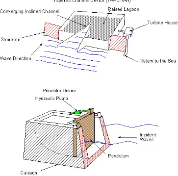
Shoreline devices have the advantage of relatively easier maintenance and installation and do not require deep water moorings and long underwater electrical cables. The less energetic wave climate at the shoreline can be partly compensated by the concentration of wave energy that occurs naturally at some locations by refraction and/or diffraction. The three major classes of shoreline devices are the oscillating water column (OWC), the convergent channel (TAPCHAN) and the Pendulor, as shown below.
7 The Tapchan comprises a gradually narrowing channel with wall heights typically 3 to 5 m above mean water level. The waves enter the wide end of the channel and, as they propagate down the narrowing channel, the wave height is amplified until the wave crests spill over the walls to a reservoir which provides a stable water supply to a conventional low head turbine. The requirements of low tidal range and suitable shoreline limit the world-wide replicability of this device.
8
9
2.2.2 The Technology - Offshore Devices
Offshore devices are situated in deeper water, with typical depths of more than 40 m. Several different designs have been deployed world-wide, with many more still at the design stage. Some of the representative devices that have been deployed are shown below:
The Swedish Hosepump has been under development since 1980. It consists of a specially reinforced elastomeric hose (whose internal volume decreases as it stretches), connected to a float which rides the waves. The rise and fall of the float stretches and relaxes the hose thereby pressurising sea water, which is fed (along with the output from other Hosepumps) through a non-return valve to a central turbine and generator unit.
The McCabe Wave Pump consists of three rectangular steel pontoons which move relative to each other in the waves. The key aspect of the scheme is the damper plate attached to the central pontoon, which ensures that it stays still as the fore and aft pontoons move relatively to the central pontoon by pitching about the hinges. Energy is extracted from the rotation about the hinge points by linear hydraulic pumps mounted between the central and two outer pontoons near the hinges. The device was developed to supply potable water (by reverse osmosis) but can also be used to generate electricity (via a hydraulic motor and generator).
The floating wave power vessel is a steel platform containing a sloping ramp, which gathers incoming waves into a raised internal basin. The water flows from this basin back into the sea through low-head turbines. In these respects it is similar to an offshore Tapchan but the device is not sensitive to tidal range.
10
11
2.3 Descriptions of Wave Power Systems
In the United States, the Pacific Northwest Generating Cooperative is funding the building of a commercial wave-power park at Reedsport, Oregon. The project will utilize the PowerBuoy technology Ocean Power Technologies which consist of modular, ocean-going buoys. The rising and falling of the waves moves the buoy-like structure creating mechanical energy which is converted into electricity and transmitted to shore over a submerged transmission line. A 40 kW buoy has a diameter of 12 feet (4 m) and is 52 feet (16 m) long, with approximately 13 feet of the unit rising above the ocean surface. Using the three-point mooring system, they are designed to be installed one to five miles (8 km) offshore in water 100 to 200 feet (60 m) deep.
An example of a surface following device is the Pelamis Wave Energy Converter. The sections of the device articulate with the movement of the waves, each resisting motion between it and the next section, creating pressurized oil to drive a hydraulic ram which drives a hydraulic motor. The machine is long and narrow (snake-like) and points into the waves; it attenuates the waves, gathering more energy than its narrow profile suggests. Its articulating sections drive internal hydraulic generators (through the use of pumps and accumulators).
12 With the Wave Dragon wave energy converter large "arms" focus waves up a ramp into an offshore reservoir. The water returns to the ocean by the force of gravity via hydroelectric generators.
Fiqure 2.4: Wave Dragon
The Anaconda Wave Energy Converter is another recent wave energy converter.
The AquaBuOY, made by Finavera Renewables Inc., wave energy device: Energy transfer takes place by converting the vertical component of wave kinetic energy into pressurized seawater by means of two-stroke hose pumps. Pressurized seawater is directed into a conversion system consisting of a turbine driving an electrical generator. The power is transmitted to shore by means of a secure, undersea transmission line. A commercial wave power production facility utilizing the AquaBuOY technology is beginning initial construction in Portugal. The company has 250 MW of projects planned or under development on the west coast of North America.