AUTO LEVEL PARKING MODEL
MOHD SALLEHUDDIN BIN SALIHIN
This report is submitted in partial fulfillment of the requirement for the award of Bachelor of Electronic Engineering (Industrial Electronic) With Honors
Faculty of Electronic and Computer Engineering Universiti Teknikal Malaysia Melaka
v
Specially dedicated to
vi
ACK OWLEDGEME T
vii
ABSTRACT
viii
ABSTRAK
ix
TABLE OF CO TE TS
CHAPTER TITLE PAGE
PROJECT TITLE i
REPORT STATUS FORM ii
DECLARATIO iii
ACK OWLEDGEME T vi
ABSTRACT vii
ABSTRAK viii
TABLE OF CO TE TS ix
LIST OF TABLES xii
LIST OF FIGURES xiii
LIST OF APPE DIXS xv
I I TRODUCTIO
1.1 Project Overview 1
1.2 Project Objectives 2
1.3 Project Problem Statement 2
1.4 Project Scope 3
1.5 Project Methodology 3
1.5.1 Project Process Flow 3
1.6 Thesis Outline 5
II LITERATURE REVIEW
2.1 Control Of A Four=Level Elevator System
x
2.1.1 Hardware Design 7
2.1.2 Description Of The Interface Circuit 8 2.1.3 Description Of The Control Panel 8
2.2 Automated Multistoried Car Parking System 10
2.2.1 System Flow 11
2.2.2 Hardware Description 12
2.3 DC Motor 15
2.4 Microchip PIC16F877A 16
2.5 IC L293D (Quadruple Half=H Driver) 19 2.6 Transmitter and Receiver Photodiode 21 2.7 IC LM324 (Quad Operational Amplifier) 22
III METHODOLOGY
3.1 Project Design 24
3.2 Project System Controller 26
3.2.1 System Input and Output 26
3.2.2 The Usage of PIC16F877A 27
3.2.3 Inputs and Outputs Connection to the
PIC16F877A 28
3.3 Motor Controller 29
3.4 Level Sensor 30
3.4.1 Position of the Sensor 31
3.5 Voltage Regulator 32
3.6 Project System Flowchart 32
3.6.1 Elevator Analysis 32
3.6.2 Parking Car 34
3.6.3 Return Car 35
xi
IV A ALYSIS
4.1 Forward and Reverse Motor Controller 40
4.2 Motor Speed Controller 42
4.3 Elevator Motor Load Analysis 43
4.4 Infrared Sensor Analysis 45
V RESULT A D DISCUSSIO
5.1 Auto Level Parking Model 48
5.1.1 Position of the Power Supply 50 5.1.2 Position of the Switch Controller 50
5.2 Discussion 52
VI CO CLUSIO A D RECOMME DATIO
6.1 Conclusion 54
6.2 Recommendation 55
xii
LIST OF TABLES
O TITLE PAGE
2.1 List and Definition of Input and Output Used 9
2.2 PIC16F877A Device Features 17
2.3 L293D Function Table 20
3.1 System Input and Output 26
3.2 L293D Function Table Control Motor 29
3.3 IR Sensor Detection 31
3.4 Project Methodology 39
xiii
LIST OF FIGURES
O TITLE PAGE
1.1 Project Flowchart 4
2.1 Block Diagram of the System Layout 7
2.2 General Scheme for the Used of an S/R Flip Flop 9 2.3 Overall Layout of the Control Panel of the Elevator 10
2.4 System Hardware 11
2.5 Usual CPU Components Program Counter, ALU,
Working Registers, and the Clock Circuits 14
2.6 Mabuchi DC Motor Series 15
2.7 PIC 16F877A 16
2.8 Pin Diagram for PIC 16F877A Microcontroller 16 2.9 Block Diagram for PIC 16F877A Microcontroller 18
2.10 Top View of L293D 19
2.11 L293D Block Diagram 20
2.12 Transmitter and Receiver Photodiode 21
2.13 IC LM324 22
2.14 IC LM324 Block Diagram 22
3.1 Project Model Front View 25
3.2 Project Model Side View 25
3.3 Pin Diagram for PIC16F877A Microcontroller 27
3.4 PIC16F877A Input and Output Connection 28
3.5 L293D Block Diagram and Motor 29
3.6 Circuit diagram for the Level Sensor 30
3.7 Position of the IR Sensor 31
xiv
3.9 Elevator Analysis Flowcharts 33
3.10 Parking Car Flowcharts 34
3.11 Return Car Flowcharts 35
3.12 Project Methodology Flowcharts 38
4.1 Motor Forward Reverse 40
4.2 Internal Circuit block in L293D 41
4.3 Voltage Waveform through the Motor 41
4.4 Speed Controller Circuit 42
4.5 Waveform of the speed control by resistor 42 4.6 Design of the balancing method for the elevator 43 4.7 Graph analyses for the elevator load effect 44 4.8 Distance of each Transmitter and Receiver 45
4.9 Function of the sensor 46
4.10 Variable Resistor 46
4.11 Arranging the sensitivity of the sensor 47
5.1 Front View of the Model 48
5.2 Side View of the Model 49
5.3 Components and Part Position 49
5.4 Position of the Power Supply 50
5.5 Parking/Return Switch Controllers 50
5.6 Manual Switch Controllers 51
xv
LIST OF APPE DIXS
O TITLE PAGE
A AUTO LEVEL PARKING PROGRAMMING 57
B DATASHEET PIC16F877A 64
C DATASHEET L293D 68
CHAPTER I
I TRODUCTIO
1.1 Project Overview
Auto level parking is a project model or just a prototype. The reason for this project been design is to present the application that can allow car user to park their car automatically on the parking lot in a certain building. The purposed of this project is to reduce space for the parking area at a small place and to park the car more easily.
The application of this project is particularly suitable for large parking of several hundred car spaces, such as public parking with hourly rates or private parking for large buildings. This project is suitable for underground parking, above ground parking and a combination of both.
2
1.2 Project Objectives
The objectives of this project to design and build a prototype or model for an auto level parking and to gather all the knowledge had been gained and put them into applications by building this model. Building this model require basic concepts as well as technical experience in order to fabricate the auto level parking structure with electronics circuitry and software programming.
The main objective of this project are as follows:
i. To design and implement the auto level parking system.
ii. To learn PIC programming and how to implement it on the hardware installation.
iii. To learn the concept of electrical DC motor system and the speed controlling system.
iv. To learn wiring system and connectivity and also the mechanical such as gearing system.
v. To learn troubleshooting and analyzing
1.3 Project Problem Statement
Nowadays, we have many type of parking system such as large parking area or level parking area in a building. This type of parking system is called manual parking. Meaning users still need to park their car their own self. This type of parking system has some sort of disadvantage such as waste time and low security system.
3
1.4 Project Scope
There are few scopes and guidelines are listed to ensure the project is conducted within its intended boundary. This is to ensure the project is heading to the right direction to achieve its objectives. This project is just a model of the auto level parking. Because of that, this project only has four level of the parking lot. First level is for the user to enter the car into the model before it park automatically. The other levels will be the parking lot for the car. This project model is dividing by two parts; Part A is the elevator to bring the car up and down. Part B is for the parking lot. In this project, PIC programming has been used as a controller system. This programming will control the whole system of this auto level parking model.
1.5 Project Methodology
1.5.1 Project Process Flow
i. Choose the project title
ii. Analysis the project scope and background
iii. Do the literature review, project objectives, problem statement, and methodology
iv. Design and drawing the model v. Prepare the hardware
vi. Prepare the software
4
[image:19.612.152.522.151.694.2]Every process of work will have its own flow to make the work be done perfectly. From the Figure 1.1 below show the process flowchart for this project. This project flow is dividing by two that is designing the model or hardware and the programming for the system.
5
1.6 Thesis Outline
CHAPTER II
LITERATURE REVIEW
This chapter presents all the literature review and some research requiring based on the auto level parking system. This literature review is primarily restricted to published research results on elevator system and automated multistoried car parking system. This literature review is required to study all the characteristic and their algorithm, requirement needed, and general idea of this project. All the information that has been collected is very important to ensure that this project achieved their objectives.
2.1 Control Of A Four8Level Elevator System Using A Programmable Logic Controller
7
2.1.1 Hardware Design
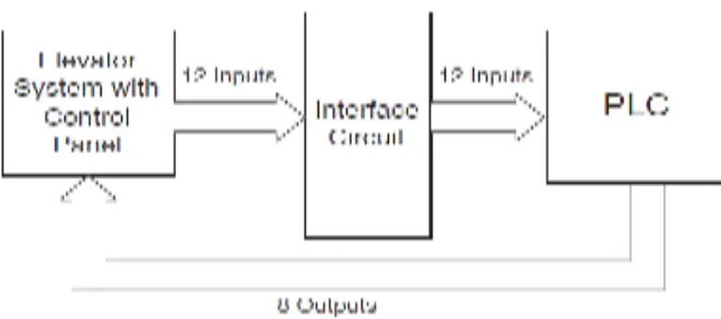
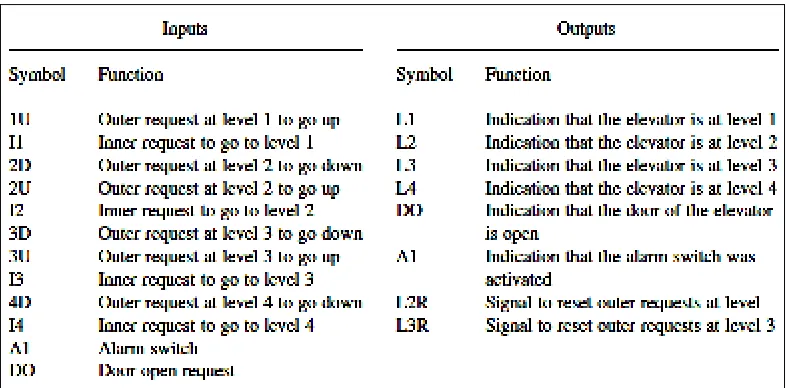
The objective of the hardware design is to develop the interface circuit between the PLC and the elevator system and the elevator control panel, with both external and internal requests. These requests are produced by push buttons that send continuous signals to the PLC when activated. Each push button is connected to an LED to identify the request placed. In addition, the four floors are represented by four LEDs, one for each level. Furthermore, an alarm switch is installed to produce a flashing signal whenever activated.
This facility was introduced to simulate the desire for a sudden stoppage of the elevator either for reasons of safety or for requests for a repair job to be carried out on the elevator. In order to obtain the desired setup, we needed to find a way to capture the pulse generated by a depressed push button. We also needed to make sure that the PLC is recognizing these signals in order for it to correctly perform the required action. As explained below, both issues were resolved by using set/reset flip flops and relays respectively.
[image:22.612.174.504.475.621.2]The block diagram of the system’s layout is shown in Figure 2.1, where both the interface between the PLC and the elevator system with the control panel are drawn.
8
2.1.2 Description Of The Interface Circuit
The hardware components used in the project is Omron Sysmac C20K PLC, 74LS04, 74LS279, 74LS156, which are inverters, SR flip flops and buffers, respectively. Also used voltage supply, push buttons, LED, resistors, relays, a switch, and connecting wires. Since the number of required inputs and outputs, i.e. 12 and 8 respectively, matches the maximum input/output capability of the PLC used, there is no need for any multiplexing or demultiplexing operations. Thus all inputs and outputs used can indirectly controlled by the PLC.
As shown in Figure 2.2, the push buttons were connected to the SR flip flops, since the PLC needs continuous signals to process, and so do the lights that indicate the requests placed. The flip flop holds the signal until the reset is activated. The reset of the flip flop is the level position for levels L1 and L4.
So when the elevator reaches one of these two levels and a request is placed the output will reset the requested signal. However levels L2 and L3 are reset by software. The reason for that is because L2 and L3 are intermediate levels. So when the elevator is traveling upwards or downwards, it has to either flash at the level it passes to show the current elevator position or service this level if its request has the appropriate direction by setting its request. In this case, it will also reset all requests associated with the serviced levels.
2.1.3 Description Of The Control Panel
9
[image:24.612.186.506.130.203.2]is displayed by the four LEDs, one for each level, which are directly controlled by the PLC according to the location of the elevator.
Figure 2.2 General Scheme for the Used of an S/R Flip Flop
[image:24.612.133.526.290.484.2]