UNIVERSITI TEKNIKAL MALAYSIA MELAKA
IMPROVEMENT OF RIDE QUALITY FOR PASSENGER
VEHICHLE USING THE MAGNETORHEOLOGICAL
DAMPER
This report submitted in accordance with requirement of the Universiti Teknikal Malaysia Melaka (UTeM) for the Bachelor Degree in Mechanical Engineering
Technology (Automotive Technology) with Honours.
by
MOHD ARIF BIN YAAKUB B071110304
920526-01-5963
i
DECLARATION
I hereby, declared this report entitled “Improvement of Ride Quality of Passenger vehicle using Magnetorheological Damper” is the results of my own research
except as cited in references.
Signature : ……….
Author’s Name : MOHD ARIF BIN YAAKUB
ii
APPROVAL
This report is submitted to the Faculty of Engineering Technology of UTeM as a partial fulfillment of the requirements for the degree of Bachelor in Mechanical Engineering Technology (Automotive Technology) with Honours. The member of the supervisory is as follow:
………
iii
ABSTRAK
iv
ABSTRACT
v
DEDICATION
vi
ACKNOWLEDGEMENT
vii
CHAPTER 1 INTRODUCTION 1
1.1 Objective 1
1.2 Scope of project 1
1.3 Problem statement 2
1.4 Vehicle dynamic 2
viii
CHAPTER 2 LITERATURE REVIEW 4
2.1 Magnetorheological fluid 4
2.2 Magnetorheological dampers 8
2.3 Semi active suspension system 10
2.4 Control system for the semi-active system 13
2.5 Ride characteristic 14
2.6 Sky-hook control 14
2.7 Suspension performance features 16
2.8 Vertical dynamic 17
2.8.1 Rigid body bounce, pitch motion and frequencies
18
2.9 Modelling aspects 19
CHAPTER 3 METHODOLOGY 20
3.1 Flow chart 21
3.2 Skyhook control strategies 22
3.3 Ground hook control strategies 23
3.4 Magnetorheological damper model 24
ix 3.8 Full Car Modelling Of Ride Vehicle Dynamic 38
CHAPTER 4 RESULT AND DISCUSSION 42 4.1 Comparison of the graph Passive suspension
system and MR control suspension system
42
CHAPTER 5 CONCLUSION AND FUTURE WORK
5.1 Conclusion 49
5.2 Recommendation Further Work 50
x
LIST OF FIGURES
2.1 No magnetic field applied 5
2.2 With the magnetic field applied 6
2.3 Valve mode 7
2.4 Direct-shear mode 7
2.5 Squeeze mode 7
2.6 MR damper 9
2.7 The degree of freedom for passive suspension system 11
2.8 The degree of freedom for semi-active suspension system 11
2.9 The degree of freedom for active suspension system 12
2.10 Scheme of the skyhook controller 15
2.11 Bounce position 18
2.12 Pitch position 18
3.1 Flow Chart 20
xi
3.3 The Ground hook control 24
3.4 Mechanical analogue of the Bouc-Wen model 24
3.5 Force tracking control of MR damper 26
3.6 The full car model diagram 27
3.7 The free body diagram of full car model 28
3.8 Sprung mass modeling 38
3.9 Unsprung mass modeling 39
3.10 Full car passive modeling 39
3.11 Full car semi-active (MR) 40
3.12 Full ride modeling (MR control) 40
xii
LIST OF ABBREVIATIONS
MR - Magnetorheological Damper
ER - Electroheological Damper
HMMWV - High Mobility Multipurpose Wheeled Vehicles
LQG - Linear Quadratic Gaussin
xiii
Fg Ground hook damping force Kgrnd Ground hook coefficient
Force acting at the vehicle body Acceleration of the vehicle Vehicle mass
Body acceleration of the vehicle
Fsfl Front left spring force Fdfl Front left damper force Fsfr Front right spring force Fdfr Front right damper force Fsrl Rear left spring force
xiv Fdrr Rear right damper force
∑ Sum of pitch moment
Pitch inertia
Pitch angular acceleration
W Distance between centre of front to the centre of rear tire or wheelbase
Roll moment of the vehicle Roll inertia
Roll angular acceleration
L Track width of the vehicle Fsfl Front left spring force Fdfl Front left damper force Mufl Front left unsprung mass
fl Front left unsprung mass vertical acceleration
xv Ksfl Front left suspension stiffness
Zufl Front left unsprung mass vertical displacement Zsfl Front left sprung mass displacement
Csfl Front left suspension damping coefficient ufl Front left unsprung mass vertical velocity
sfl Front left sprung mass velocity
Ktfl Front left tire stiffness Zrfl Front left road profile
Ksfr Front right suspension stiffness
Zufr Front right unsprung mass vertical displacement Zsfr Front right sprung mass displacement
Csfr Front right suspension damping coefficient ufr Front right unsprung mass vertical velocity sfr Front right sprung mass velocity
Ktfr Front right tire stiffness Zrfr Front right road profile Ksrl Rear left suspension stiffness
Zurl Rear left unsprung mass vertical displacement
xvi Ktrl Rear left tire stiffness
Zrrl Rear left road profile
Ksrr Rear right suspension stiffness
Zurr Rear right unsprung mass vertical displacement Zsrr Rear right sprung mass displacement
Csrr Rear right suspension damping coefficient urr Rear right unsprung mass vertical velocity srr Rear right sprung mass velocity
1 The objective and scope for this project is clearly states in this chapter. The introduction of vehicle dynamic and ride quality are also discusses in this chapter for the more understanding about this project. There is some discussion on the sub-title of ride quality that is problem of ride quality that affected on vehicle and human.
1.1 Objective
To developed an equation for magnetorheological damper for passenger vehicle.
To developed a control algorithm for magnetorheological damper that can improve the ride quality of passenger vehicle.
1.2 Scope Of Project
Development the 7-DOF of vehicle ride vehicle dynamic equation
Development the 7-DOF of ride vehicle dynamic using the Matlab simulink software.
Development a control algorithm of magnetorheological damper.
INTRODUCTION
2
1.3 Problem Statement
Ride comfort is also one of the criteria that must be considered in automotive industry. From the criteria, people are attracted to experience the quality of good vehicle ride and controlling. The important of ride comfort is to improve vehicle stability, provide comfortable aspect to the drivers and give the maximum safety for vehicle and driver. For the driver, especially in term of healthy, the vehicle with a very good ride quality is the best choice to make.
Base on the research, a poor ride quality can cause bad injuries to the back bone and serious back pain. It also makes the bone joint feel uncomfortable when riding the vehicle. So with this good ride quality, the kind of pain can be avoided.
When the vehicle is driven on the different type of road, there is some vibration that can cause the joining part become easily worn out. If the vehicle use magnetorheological damper as the suspension system, it can reduce the vibration and make the joining part in a vehicle is long lasting.
1.4 Vehicle Dynamic
Vehicle dynamic is the branch of engineering that relates tyre and aerodynamic forces to overall vehicle acceleration, velocities and motions due to
Newton’s Laws. It encompasses the behaviour of the vehicle as affected by tyre, driveline, chassis characteristics and aerodynamic. This subject is complex because it involves large number of variable.
3 modern vehicle now are provided with many electronic system that can improve the handling stability, provided comfortable driving and increase the passenger safety and health. This feature can see on the vehicle such as EBD, ABS, VSC (vehicle stability control) and others.
Ride are related to the vibration of the vehicle on the irregular surface and its effect on passenger and goods. Therefore, the theory of vehicle dynamic is concerned with the study of handling, performance and ride relationships with the vehicle design under various operating conditions. The performance of the vehicle that response to force imposed is by accomplished the motion in accelerating, braking, cornering and ride. The study of vehicle dynamics must involve the study of how the force is produced.
The ride quality is measured in terms of the level of isolation from road inputs in the suspension transfers to vehicle without any problem on vehicle control. Ride is the major component of the vehicle comfort and the problems will occur
when the vehicle’s suspension failed to absorb force from the tire on the different
4 There are many history of suspension system used in vehicle and how the passive suspension system is developed until it becomes the semi-active suspension system. This chapter has discusses of literature review about the semi active system. A history about the Magnatorheological Damper that use in the semi active suspension system also consist in this chapter.
2.1 Magnetorheological Fluid
Lately, the magnetorheological (MR) dampers received more attention as semi-active system actuator because of their fast response to applied magnetic field and have a compact size. In 1948, Jacob Rabinow was the first person that observed the effect of magnetorheological damper. Researcher began in late 1980s and 1990s to get serious about developing the commercial viability of MR fluids, especially when others technologies began to made their practically used and real possibility. Sensors technology, microprocessors, processing speed and increasing electronic
content have make control possibilities that did not exist in Rabinow’s time.
MR fluid is defines as the magnetically induced fibrillation of micrometer-sized, which magnetic particles suspended in a low viscosity fluid. With the effect of magnetic field, the particles of MR fluid associated themselves with respect the magnetic field and form into columns or chains that make the viscosity of the MR fluid change. Without any magnetic field produce, the MR fluid has the properties of a Newtonian fluid.
5 MR fluid is composed of oil and varying percentages of iron particles that have been coated with an anti-coagulant material. When inactive, MR fluid behaves as ordinary oil, but it uncovered to a magnetic field, micron size iron particles that are distributed throughout the fluid align themselves along magnetic flux line (James Poynor, 2001). The changes in physical property of MR fluid are resulted from the chain-like structures between paramagnetic MR particles in the low permeability solvent.
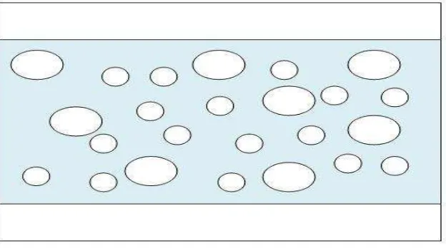
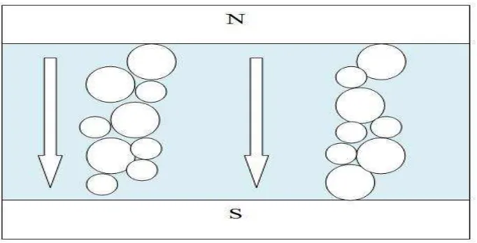
At the normal state, MR fluid shows the isotropic Newtonian behaviour because the MR particles move freely as shown in Figure 2.1. But, when the magnetic field applied to the MR fluid, it shows anisotropic Bingham behaviour and resist to flow or external shear force because the MR particles make a chain structure as shown in Figure 2.2. From this property, torque or force of application devices can be easily controlled by the intensity of the magnetic field.
6
Figure 2.2: With the magnetic field applied
MR fluid have many attractive features, including high yield strength, low viscosity and stable hysteretic behaviour over a broad temperature range (Carlson, 1994). Anyway, the barrier of their widespread commercial and the principle handicap of fluids is received in many areas but still relative high cost.