MODELING WIRE ANTENNA USING 3D FINITE DIFFERENCE-TIME DOMAIN (FDTD) METHOD IN GRAPHICAL USER INTERFACE (GUI) FOR RADIATION
PETTERN EVALUATION
SITI NURSYUHADA BINTI MAT NASIR
This Report Is Submitted In Partial Fulfillment Of Requirement For The Degree of
Bachelor In Electronic Engineering (Telecommunication Electronic)
Fakulti Kejuruteraan Elektronik dan Kejuruteraan Komputer
Universiti Teknikal Malaysia Melaka
v
It is only befitting that I dedicated this humble work to the noble and illustrious prophet, Muhamad SallallahuAlaihiWasallam, addressed by Allah SubhanahuWata‟ala as the “Unlettered” Prophet, yet, the Master of the most extensive knowledge, foretold in previous scriptures, and the Mercy for the Worlds.
Special dedication to my loving parents, Mat Nasir bin Zakaria and Hasnira binti Abdullah, also to all my supported siblings, my kind hearted Encik Fauzi bin Mohd
vi
ACKNOWLEDGEMENT
Alhamdulillah, all praise to thank to Allah SWT the almighty for giving me the Rahmah to finish my Project Sarjana Muda II successfully. Thanks to Ilahi for the opportunity given and helped make easier the entire task project given as long as this semester. After work hard for whole semester, finally I finished my Project Sarjana Muda II with fully satisfaction.
Special thanks to my kind hearted supervisors Mr. Fauzi bin Mohd Johar, for the opportunity given to me to do this project. Thank a lots for the her endless support and ideas, during which he has been patiently supervising my progress and encouraged me to do this project in the right way. He never tired to teach me step by step until I can do it independently. With full of hope, Allah SWT bless him and family.
Then, I would like to thanks for my family, especially my loving parents Mat Nasir bin Zakaria and Hasnira binti Abdullah and my siblings because always be behind me. Thank you for the support and encouragement. They are always advising me to perform the best in any field that I involve. Without them, I wouldn‟t to complete my thesis project with successful.
vii
ABSTRACT
The Finite-Difference Time-Domain (FDTD) method is one of known electromagnetic numerical tool that used for design and analysis the antenna. Whereas this method is simpler than Method of Moments (MoM) or Finite Element Method (FEM) and it is space time based domain as a result benefited to wide band frequencies application. The purpose of project is to develop a simulator based on 3D-FDTD method
viii
ABSTRAK
Kaedah Finite-Difference Time-Domain (FDTD) merupakan salah satu
perkakasan numerikal elektromagnetik yang digunakan untuk merekabentuk dan
menganalisa antena. Di mana kaedah ini lebih ringkas daripada Method of Moments (MoM) atau Finite Element Method (FEM) dan ianya berdasarkan ruang masa domain
ix
CONTENTS
CHAPTER TITLE PAGE
PROJECT TITLE
STATUS REPORT FORM STUDENT DECLARATION SUPERVISOR DECLARATION DEDICATION i ii iii iv v
ACKNOWLEDGEMENT vi
ABSTRACT vii
ABSTRAK viii
CONTENT ix
LIST OF FIGURE xii
LIST OF APPENDIX xiv
CHAPTER I INTRODUCTION 1
1.1 PROJECT OVERVIEW 1
1.2 OBJECTIVES 2
1.3 PROBLEM STATEMENT 3
1.4 SCOPE OF PROJECT 4
CHAPTER II LITERATURE REVIEW 9
2.1 FINITE-DIFFERENT TIME-DOMAIN(FDTD) 2.2 NEAR-FIELD TO FAR-FIELD
x
2.3 ABSORBING BOUNDARY CONDITION 2.3.1 Introduction
2.3.2 Perfectly Matched Layer (PML)
2.3.3 Convolutional Perfectly Matched Layer (CPML)
18 18 19 20
2.4 THIN WIRE FORMULATION 2.5 FDTD SOURCE
36 37 . 2.5.1…..Active And Passive Lumped Elements
2.5.2 Gaussian Waveform
2.5.3 Cosine Modulated Gaussian Waveform
37 40 41
CHAPTER III ANTENNA 42
3.1 THIN WIRE ANTENNA 42
3.1.1 Array Dipole Antenna 3.1.2 Spiral Antenna
3.1.3 Meander Spiral Antenna 3.2 PARAMETER OF ANTENNA
3.2.1 Radiation Pattern 3.2.1 Directivity
3.2.2 Gain
43 44 46 47 47 49 50
CHAPTER IV METHODOLOGY
4.1 IMPLEMENTATION PLANNING PROJECT 4.2 PROJECT METHODOLOGY
52
xi
CHAPTER V RESULT AND ANALYSIS
5.1 FDTD INPUT PARAMETER
5.2 ANTENNA RADIATION PATTERNS 5.3 COMPARISON RESULT BETWEEN THE ANTENNA
57
57
57 61
65
CHAPTER VI
REFERENCES
APPENDIX
CONCLUSION AND SUGGESTION 6.1….INTRODUCTION
6.2 CONCLUSION
6.3 SUGGESTION AND FUTURE WORKS
68 68
69 70
71
74
xii
LIST OF FIGURE
FIGURE TITLE PAGE
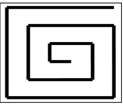
1.1 Spiral 5
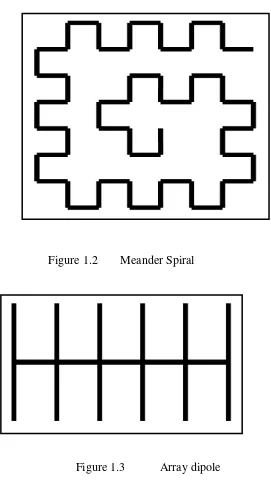
1.2 Meander Spiral 6
1.3 Array dipole 6
2.1 Yee Cell 11
2.2 Position of the electric and magnetic fields in Yee‟s scheme
12
2.3 Equivalence principle (a) original problem (b) equivalent problem
18
2.4 The CPML on the plane boundary 22
3.1
3.2
(a) Application of Faraday‟s Law for derivation of the thin wire model. (b) H-field components updated using the thin wire model and integration path for calculation of the current I
Meander Line Structure
43
47 3.3 Different lobes of a radiation pattern with main lobe
oriented with an axis.
48
3.4 A three dimensional radiation pattern with its direction of maximum radiation aligned with the z-axis. The electric field components and the Poynting vector are shown.
xiii 4.1 4.2 5.1 5.2 5.3 5.4 5.5 5.6 5.7 5.8 5.9 5.10
Flowchart of Project Planning Explicit FDTD Procedures Simulation Layout on GUI
Result/output on GUI for antenna array dipole Result/output on GUI for antenna spiral
Result/output on GUI for antenna meander spiral Radiation pattern of array dipole antenna
Radiation pattern of spiral antenna
Radiation pattern of meander spiral antenna
Comparison radiation pattern for three types of antennas in xz-plane
Comparison radiation pattern for three types of antennas in yz-plane
xiv
LIST OF APPENDIX
NO TITLE PAGE
A B
FDTD formulation
Main program of FDTD
74 77
C B C
FDTD formulation
Main program of FDTD
Define problem space program
CHAPTER I
INTRODUCTION
This chapter elaborates the project background, project objectives, problem statements, scope of work, methodology and lastly project planning.
1.1Project Overview
2
being solved. The advantage of FDTD is simple method to implement numerically and time based simulation as result better for obtaining wideband frequency response.
In order to compute the antenna radiation pattern which is in the far away region from radiated antenna the near-field to far-field (NFFF) transformation technique and also Fast Fourier Transformation (FFT) will be implemented.
1.2 Objectives
The objective of this project is:
i. To implement MATLAB in wire antenna modeling.
ii. To model straight line spiral wire antenna using 3D finite difference-time
domain (FDTD).
iii. To analyze the radiation pattern of thin wire antenna.
3
1.3 Problem Statement
In this world today, many people has their own creativity to upgrade the every existing software to become a new software depend on their criteria that they want. If analytical method is used, theoretical of fundamental must be strong to designing any structure required. Until now, we have assumed that all of the objects in the FDTD problem space conform to the FDTD grid. The FDTD method has gain tremendous popularity of the past decade as a tool for solving Maxwell‟s equations. It is based on simple formulations that do not require complex asymptotic. The FDTD technique is easy to implement using parallel computation algorithm. Besides that, these features of the FDTD method have made it the most attractive technique of computational electromagnetic for many microwave devices and antenna application. Thus, some subcell modeling techniques are develop to model geometries that do not conform to the
grid or have dimensions smaller than cell dimensions. One of the most common such geometries is a thin wire that has a radius less than a cell size. Thus, we can use FDTD program to model the thin wires as a model techniques subcell. There are various techniques proposed for modeling thin wires. In this project we use is based on Faraday's law contour-path formulation. Here we can see FDTD is a very versatile modeling technique. It is a very intuitive technique, so users can easily understand how to use it, and know what to expect from a given model.
Furthermore, others problem statement that we can define is, in perspective computational methods in electromagnetic which is various methods that may be employed for the analysis of boundary value problems in electromagnetic. As shown, the analysis may be based on theoretical approach and/or experimental measurements.
i. Analysis may be used to reduce the number of costly tests on prototypes by supporting the design process.
4
iii. Analysis can provide an understanding of the operating principles that could be useful for a new design, for modification of an existing design, and for the development of new configurations.
1.4 Scope of Works
1. Understanding FDTD Algorithm
This work presents the development of a modeling wire antenna using 3D FDTD
method in graphical user interface (GUI) for radiation pattern evaluation. The formulation of the implemented FDTD algorithm is described, as well as the analysis of its fundamental properties. A description of the complementary techniques and algorithms that allow the effective implementation of a simulator for the analysis of problems of engineering value is also presented. These include a Convolutional Perfectly Matched Layer (CPML), a thin-wire model, excitation source models and a near-to-far-field transformation. The stated above techniques are implemented in a modular fashion and integrated into a graphical user interface that, besides allowing the configuration and three-dimensional visualization of the structures being analyzed, also features a non-uniform mesh generation algorithm that automatically performs the discretization of the 3D objects.
In this project we also use techniques in computational electromagnetic (CEM),
5
the electromagnetic phenomenon and are therefore based on discretizations of differential or integral formulations of Maxwell‟s equations. Both integral and differential equation based numerical methods can be divided in two parts namely frequency domain and time domain.
2. Familiarize FDTD Program
In this project, the starting point for the construction of an FDTD algorithm is Maxwell‟s time domain equation. The time-dependent Maxwell‟s equations in a region of space without imposed electric or magnetic current sources, but that may have materials that absorb electric or magnetic field energy, are given in differential form, by Faraday‟s law and Ampere‟s law. Then, it converts into scalar Maxwell‟s equations for 3D FDTD. After make a Scalar Maxwell‟s equations for 3D FDTD, the Maxwell‟s will discretized where it analyzed related to time dependent Maxwell‟s equation that introduce by Yee cell.
[image:19.612.204.454.454.674.2]3. Design Antenna
6
Figure 1.2 Meander Spiral
Figure 1.3 Array dipole
7
4. Develope Graphical User Interfaces (GUI)
A graphical user interface (GUI) is a graphical display in one or more windows containing controls, called components that enable a user to perform interactive tasks. The user of the GUI does not have to create a script or type commands at the command line to accomplish the tasks. Unlike coding programs to accomplish tasks, the user of a GUI need not understand the details of how the tasks are performed. However, creating a GUI can make the review of current system and equipment conditions much easier for the facility personnel.
Construction of the GUI encompasses: -
Creating forms/background screens: A form is a graphic object that may or may
not have a background image associated with it. A form without an associated background image is a blank screen onto which you can put other graphic objects. Background images are drawings made with any standard drawing tool or digital pictures from any source that are saved in or converted to BMP, PCX or JPG format.
Attaching these forms/background images to the GUI by filename.
Associating configured point groups with the forms/background images.
Creating graphic objects on the forms/background images. These objects can be:
i. Point Status boxes (Input points or Output points) ii. Static Text
iii. Hot Spot Form Links iv. Animations
8
Configuring these objects with text descriptions, point values, links to other
graphics, etc.
CHAPTER II
LITERATURE REVIEW
Chapter two is about literature review regarding the project. It contains method to do research, theory used to solve problem in this project and so on.
2.1 Finite Different Time- Domain (FDTD)
10
i. Faraday‟s law
M E t
B
(2.1.1a) Where,
E= electric field strength vector in volts per meter
M= magnetic current density vector in volts per square meter B= magnetic flux density vector in webers per square meter
ii. Ampere‟s Maxwell law
J H t
D
(2.1.1b) Where,
H= magnetic field strength vector in amperes per meter J= electric current density vector in amperes per square meter D=electric displacement vector in coulombs per square meter